Several recent advances point the
way toward real-time holographic television for telepresence, entertainment,
and teleoperation. This article introduces the concepts and requirements for
such systems, then presents the MIT Media Lab's work to make them practical
and inexpensive.
by V. Michael Bove, Jr., and Daniel Smalley
THE NOTION of holographic television appeals to the popular imagination, figuring prominently
in science-fiction movies and carrying enough cachet that the word "holographic"
is often applied to systems that are not really holographic and sometimes not even
3-D, such as the "Pepper's ghost" illusions that have been used to re-create deceased
celebrities onstage. Holographic TV also potentially provides some important technical
advantages in that unlike two-view 3-D TV, it supplies in a consistent fashion all
the visual cues to object shape and position, including focus ("accommodation")
and motion parallax, increasing both viewer comfort for extended viewing and perceptual
accuracy for precise tasks.
Research since the early 1960s has attempted to build true holographic television,
but until very recently the prospect has seemed distant. The authors' group has
for several years concentrated on developing holographic displays suitable for consumer
applications, adding constraints of mass manufacturability, low cost, and compatibility
with mass-market computational resources such as might be found in PCs or game consoles.
A resurgence of consumer interest in 3-D displays, combined with several relevant
technological developments, makes this an opportune time to explore re-imagining
holographic displays as part of a home in the near future rather than in fictional
spacecraft in the far-off future.
Before we consider technical requirements for building such a device, it is important
to define precisely what a holographic display is, namely, a system that uses diffraction
of light to reconstruct light wavefronts (or lightfields) associated with a desired
visual scene. It is sometimes added that the diffraction pattern should be generated
by interference between a coherent reference beam and coherent light reflected by
a scene (or at least by a computational simulation of the interference), but for
a display designer the physical characteristics of the necessary diffraction patterns
are what matters.
Like all 3-D displays, holographic displays are bound by the behavior of light
and – despite cinematic special effects to the contrary – cannot create
images in free space or project them across a room. As shown in Fig. 1, from the
point of view of the viewer, all parts of a reconstructed object must have the display
behind them.
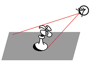
Fig. 1: From the eye's viewpoint, an object
reconstructed by a hologram cannot extend past the edges of the display device.
Engineering Requirements
The realism of holographic displays and also the difficulty
of building them can be traced to the physics of diffraction. A device is required
– usually called a spatial light modulator (SLM) – that can change the
amplitude (by varying its transmittance) and/or phase (by varying its index of refraction)
of light waves passing through it with a fine enough pixel pattern that diffraction
over a useful range of angles (which will be the viewing angle of the display) occurs.
For typical display applications this means a pixel pitch of about the same size
as the wavelength of visible light (or around half a micron).
Half-micron pixels may be smaller than the pixels in typical current microdisplays,
but an even bigger challenge lies in the fact that physics constrains the pixel
size to stay the same no matter the size of the display. Thus, such a display will
need about 2 million pixels per scan line per meter of image width. It's not too difficult to make a tiny direct-view
holographic image by illuminating a micro-display with a laser, but scaling this
up to useful dimensions by tiling such displays together is a complicated proposition.
Tiling of small devices nevertheless has been employed by several researchers to
create larger images; if the device is fast enough, the tiling can also be done
optically, where one device images in several positions sequentially.
A strategy that relaxes the need for such small pixels is to make
a hologram with a smaller view angle (and thus larger pixel pitch in the SLM) and
then use a steerable light source to direct the hologram where an eye tracker sees
the viewer's pupils.1 The pixel count and computational requirements
reduce significantly if the hologram is made to have parallax only in the horizontal
direction, as the vertical resolution then reduces to that of an ordinary television
image, and the computation of each scan line can be carried out independently.
Diffraction
For clarity, the following diffraction discussion will
be done in one dimension, with the extension to two dimensions straightforward (for
a horizontal-parallax-only display, the process will happen in only one dimension).
If a beam of monochromatic light enters a sinusoidal diffraction pattern, some
will pass straight through (the undiffracted or zero-order beam) and beams will
also come out at an angle to either side of the zero-order beam (the first-order
diffracted beams). The resulting angle is a function of the ratio of the wavelength
of the light to the spatial frequency of the pattern, while the amount of light
that is diffracted is a function of the contrast of the pattern. Note here that
the R/G/B illuminators will need to be monochromatic, as broadband illumination
will diffract across a range of angles, leading to a blurry image.
Such grating patterns are created in optical holograms through
interference, but the mathematics for synthesizing them from a three-dimensional
model of a scene are tractable. This process can be carried out similarly for a
computer-graphics model or for real imagery if sufficient information about the
real scene can be captured.
If the spatial frequency of the sinusoid varies (a "chirped" grating),
as in Fig. 2, and the pattern is illuminated with collimated light, beams at the
higher-frequency end will be diffracted at more of an angle than those on the other
end, giving the appearance that the light is coming from a point emitter.
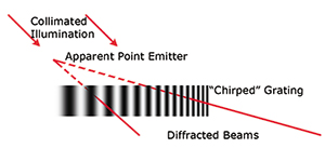
Fig. 2: Because
a "chirped" diffraction pattern bends light by varying angles, when it is illuminated
by collimated light, the result appears to be a point emitter at a particular
(x,y,z) position. A scene can be built up by superposing about as many of these
as there would be pixels in an ordinary image of similar apparent resolution.
Note that for this diffraction method to work, there must be a
mechanism – which could be as simple as a barrier – for keeping the
undiffracted and opposite-order light from reaching the viewer's eyes. It should
be apparent that a 3-D scene could be built up by summing up chirped gratings corresponding
to the points making up the scene. Such calculations are within the capabilities
of modern PC or game-console graphics processors.2
Capture and Transmission
It is commonly assumed that the massive pixel count
of display holograms makes transmitting real-time holographic television nearly
impossible, and even if data compression could somehow reduce the data rate to something
manageable, the requirement for coherent illumination of the scene and extremely
short exposure times for moving imagery (because the scene has to be stationary
to within a small fraction of a wavelength of light during the exposure) would still
render the process impractical. Nevertheless, since the early days of holography,
analysis and experiments have been carried out for coherent capture and real-time
transmission.3-5
Recent advances in two areas have opened up an alternative approach:
non-holographic capture and calculation of the holographic interference pattern
at the receiving end. Ordinary cameras have become small and inexpensive enough
to permit building dense arrays of them, while small lightfield and rangefinding
cameras have also become available. The outputs of each of these image acquisition
strategies are more compact and easier to transmit than the holograms that would
result from capturing the same scenes at the equivalent image resolutions, and current
graphics processors and digital signal processors provide enough processing to do
the necessary diffraction-pattern computation.
Thus, researchers have recently been able to demonstrate scene
capture for holographic displays using a camera array,6 a lightfield
camera,7 or a rangefinding camera.8 The authors' group at
the MIT Media Lab has shown that the Microsoft Kinect can be used as the camera
for a holographic television system, with Internet transmission of the resulting
data and conversion to horizontal-parallax-only holograms at video rates on a standard
PC with three graphics cards. Because the Kinect produces perspective views and
the rendering algorithm needs an orthographic camera in the parallax direction,
it is necessary to perform calibrated geometric correction as part of the process.
Because a hologram captured with a single camera will have missing occluded regions
visible from viewer positions far from that of the camera, for complex scenes or
displays with large viewing angles it may be necessary to merge data from more than
one rangefinding camera, requiring yet more calibration and correction. The resulting
holograms have been demonstrated on both our display and a refreshable polymer display
developed by the University of Arizona, College of Optical Sciences (Fig. 3).
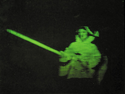
Fig. 3: This hologram was generated
from a Kinect camera and displayed on a refreshable photorefractive polymer
display. Courtesy University of Arizona College of Optical Sciences.
Display Devices
Several generations of holographic video displays have
been built at the MIT Media Lab since the groundbreaking Mark I display premiered
by Stephen Benton and his students in 1989.9 Our current display project
continues with the Scophony geometry used in its predecessors, where instead of
a common light-modulator technology, the diffraction patterns are created by acoustic
waves in a transparent material; as the pattern moves with the speed of sound, such
systems need a mechanical scanner to provide a stationary hologram. Recent systems
in our laboratory have employed our own lithium niobate guided-wave light modulator
in place of the earlier bulk-wave acousto-optic modulators. These devices –
similar to surface-acoustic-wave filters – can be fabricated with a modest
two-mask process. In a guided-wave modulator, a waveguide is created just under
the surface of the material, light is coupled into the waveguide, and diffraction
is created by surface acoustic waves. One of our prototype modulators is shown
in Fig. 4.
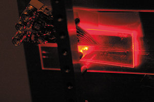
Fig. 4: In
this photograph of a guided-wave light-modulator chip, laser light enters at
left and diffracted light exits at right.
Our ultimate target is to fabricate devices with 480 or more independent
waveguides, providing sufficient bandwidth to support large displays, but our immediate
goal is to demonstrate a full-color horizontal-parallax-only 100-mm-wide proof-of-concept
desktop display of SDTV resolution with a bill of materials in the hundreds of dollars.10
Figure 5 shows the basic architecture: the light output from the
modulator passes through a lens, horizontal and vertical scanners (where the vertical
scanner will eventually not be needed when the modulator has as many channels as
the display has scan lines), a parabolic mirror, and a vertical diffuser. Because
the diffracted light has a rotated polarization from the zero-order beam, removing
the latter can be done with a polarizer. We first verified the operation of the
display optics with a bulk-wave modulator (Fig. 6 shows a small full-color image)
and are now using our guided-wave modulator. Full details of our experiments will
be presented in an upcoming publication, but the optical design has proven to work,
and Fig. 6 shows a full-color (though not 3-D) image from the display system.
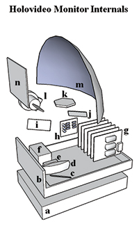
Fig. 5: This prototype display
consists of a power supply (a), folded aluminum chassis (b), mirrors i and j
(c), transform lens (d), light modulator (e), laser source (f), modulator driver
cards with DVI-A inputs (g), phased-lock-loop control to drive the polygon (k),
vertical scanner (l), parabolic reflector (m), and anisotropic diffuser (n).
The vertical scanner will not be needed when the number of channels in the modulator
increases to match the number of scan lines in the hologram.
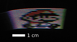
Fig. 6: This single view of
a small holographic stereogram test image (only 26 scan lines, not full screen)
was displayed on the system shown in Fig. 5.
Holographic Television: A Work in Progress
A brief article such as this can just touch upon the
basic principles; readers interested in exploring in depth the current state of
display holography may want to look at a comprehensive recent technical overview
by the author.11 Much research and development remains to be done before
holographic television is an everyday consumer product, but the practicality of
real-time holographic viewing is being enabled by progress in a variety of technologies.
For a Q&A with V. Michael Bove about the processing demands of holographic
television,
see the October 2012 issue of Information Display.
Acknowledgments
Research described in this article has been supported
by consortium funds at the MIT Media Lab and by a gift from Intel Corp. We also
thank NVIDIA for providing graphics hardware used in this work.
References
1R. Haussler, S. Reichelt, N. Leister, E.
Zschau, R. Missbach, and S. Schwerdtner, "Large real-time holographic displays:
From prototypes to a consumer product," Proc. SPIE Stereoscopic Displays and
Applications XX 7237, 72370S (2009).
2Q. Y. J. Smithwick, J. Barabas, D. E. Smalley,
and V. M. Bove, Jr., "Interactive holographic stereograms with accommodation cues,"
Proc. SPIE Practical Holography XXIV 7619, 761903 (2010).
3E. N. Leith, J. Upatnieks, B. P. Hildebrand,
and K. Haines, "Requirements for a wavefront reconstruction facsimile system," J.
Soc. Motion Picture Television Eng. 74, No. 10, 893–896 (Oct. 1965).
4L. H. Enloe, J. A. Murphy, and C. B. Rubinstein,
"Hologram transmission via television," Bell Syst. Tech. J. 45, No.
2, 335–339 (Feb. 1966).
5R. J. Doyle and W. E. Glenn, "Remote real-time
reconstruction of holograms using the Lumatron," Appl. Opt. 11, No.
5, 1261–1264 (1972).
6P-A. Blanche, A. Bablumian, R. Voorakaranam,
C. Christenson, W. Lin, T. Gu, D. Flores, P. Wang, W.-Y. Hsieh, M. Kathaperumal,
B. Rachwal, O. Siddiqui, J. Thomas, R. A. Norwood, M. Yamamoto, and N. Peyghambarian,
"Holographic three-dimensional telepresence using large-area photorefractive polymer,"
Nature 468, No. 7320, 80–83 (2010).
7R. Oi, T. Mishina, K.Yamamoto, and M. Okai,
"Real-time IP-hologram conversion hardware based on floating point DSPs," Proc.
SPIE Practical Holography XXIII 7233, 723305 (2009).
8 J. Barabas, S. Jolly, D. E. Smalley, and
V. M. Bove, Jr., "Diffraction specific coherent panoramagrams of real scenes," Proc.
SPIE Practical Holography XXV 7957, 795702 (2011).
9P. St.-Hilaire, S. A. Benton, M. Lucente,
M. L. Jepsen, J. Kollin, and H. Yoshikawa, "Electronic display system for computational
holography," Proc. SPIE Practical Holography IV1212, 174–182
(1990).
10D. Smalley, Q. Smithwick, J. Barabas, V.
M. Bove, Jr., S. Jolly, and C DellaSilva, "Holovideo for everyone: a low-cost holovideo
monitor," Proc. 9th International Symposium on Display Holography (ISDH 2012)
(2012).
11V. M. Bove, Jr., "Display holography's
digital second act," Proc. of the IEEE 100, No. 4, 918–928 (2012).
•
V. Michael Bove, Jr., heads the Object-Based
Media Group at the MIT Media Lab. He is co-author with the late Stephen Benton
of the book Holographic Imaging
(Wiley, 2008) and served as co-chair of
the 2012 International Symposium on Display Holography. He can be reached at vmb@media.mit.edu.
Daniel Smalley is a doctoral candidate in
the Object-Based Media group at the MIT Media Lab. He can be reached at desmalley@gmail.com.