Automotive Applications for Passive-Matrix OLEDs
Automotive Applications for Passive-Matrix OLEDs
Passive-matrix OLED technologies offer some excellent advantages for automotive designers. However, consideration also needs to be given to factors that could affect design performance, including luminance decay, burn-in, power consumption, and color availability.
by Jeff Hatfield, Yoshiyuki Kobayashi, and Akihiro Nonaka
DUE TO improvements in passive-matrix OLED (PMOLED) technology, Futaba Corp. has successfully launched PMOLED displays into the automotive OEM market. One example is a display appearing in the 2015 Hyundai Sonata (Fig. 1). The digital information in the center area of this instrument cluster is seamlessly integrated with the analog displays and automotive icons in the rest of the cluster, due to the real black level of the emissive PMOLED display, which has a dark-room contrast ratio between image and background of more than 100,000:1. PMOLED technology represents a giant step forward for vehicle technology in terms of design flexibility and viewing angle. It is not a one-size-fits-all technology, however, as we will describe throughout the rest of this article.
As Fig. 1 indicates, PMOLED displays are currently in production today for an automotive cluster application, but other applications are a good fit for PMOLEDs as well, including climate-control displays, rear/front-seat status indicators, etc. These smaller applications are an ideal use for PMOLED displays based on the thin-packaging and custom-design possibilities it offers. (Futaba has other PMOLED displays in automotive development but cannot share details at this time.)
PMOLED, as the name implies, is a passively driven array of self-emissive pixels creating a graphical-type display. Although fixed-segmented OLEDs that are statically driven, and currently being used for automotive applications, this article will focus mainly on PMOLED graphical displays. PMOLED technology offers some distinct advantages, such as fast response times (temperature independent), self-emissive (thin packaging with no backlight), high contrast, and wide viewing angle. On the other hand, other aspects that can affect design performance include luminance decay, burn-in, power consumption, and color availability. As with any display technology, the end user should consider both the positive and negative aspects of the chosen technology.
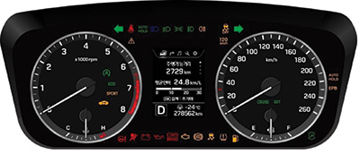
Fig. 1: This instrument-cluster meter with a 3.5-in. PMOLED display (center section of display) manufactured by DENSO for the Hyundai Sonata shows seamless integration of the display, with no display outline and no different background since the contrast ratio is more than 100,000 to 1.
Luminance Output
PMOLED displays are limited in luminance output based on the scan rate and energy available to illuminate the organic pixel. In general, the higher the scan (frame) rate, the lower the luminance. This scan scheme currently limits the practical automotive usage of PMOLED displays to an approximate array size of 168 × 256 pixels, putting the industry common QVGA (quarter video graphics array), or larger-type display applications, out of reach for PMOLED displays. This same scan scheme limit, in turn, makes only monochrome applications practical, as the color filtering needed for a color PMOLED display, using white-emitter material reduces the luminance further than that of a monochrome PMOLED display, making the luminance too low for automotive usage.
For reference, a typical automotive white monochrome PMOLED display can provide 300 cd/m2 (500 cd/m2 for fixed-segmented-type OLEDs), with white being the most common monochrome color, but blue and red also being possibilities. The aforementioned luminance is after the inherent automotive-grade circular
polarizer (CPL) deemed necessary to enhance contrast for automotive applications has been incorporated. Luminance can also vary at the pixel level to allow gray-scale appearances by using available IC and software configurations.
Dead-Front Appearance
Due to the nature of PMOLED display’s self-emissive technology, there is no backlighting required because, as the name implies, the PMOLED display is self-emissive; i.e., it creates its own light without the need for backlighting. Consequently, an all-off pixel condition will create a dead-front appearance from the PMOLED display. (A “dead-front” appearance allows the display to be flush with the rest of the panel, so that the light is only visible when the display is illuminated.) The other consideration for a dead front is to apply enough front-lens darkening filtering to ensure the inherent OLED mechanical structure remains hidden in the final application.
Contrast Ratio
Figure 2 shows the typical PMOLED display contrast ratio across a variety of ambient
conditions.
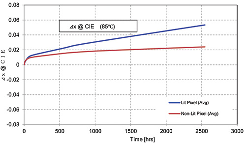
Fig. 2: A typical PMOLED display contrast ratio (CR) is compared to ambient illumination. For reference, the typical CR for a similar appearing LCD in low ambient is about 1000:1.
Color Availability
As mentioned above, the color palette available for PMOLED displays is not infinite. Due to the special color ratio of organic material making up the pixel,
available color ranges are limited and consideration must be taken to match the PMOLED display capabilities to end-user color coordinates.
The CPL filter can provide some additional filtering, but it too will have finite color characteristics.
Viewing Angle
Although a PMOLED display is considered to have a wide viewing angle, as evident in Fig. 3, it is important to consider the effects of color shift at extreme angles. This phenom-enon for PMOLED displays is due to variations of light refractions inside the PMOLED display; as the viewing angle increases, it causes a shift in the light wavelengths that are visible to the eye. It should be noted that although the display viewing angle in a dashboard is fixed, there is a wide range of possible locations for a display’s dashboard or center stack application placement. An OLED display’s wide viewing angle, with limited color and luminance change, offers flexibility to designers in terms of center-stack location — close to the hand rest, close to the windshield, or in the instrument-cluster meter.
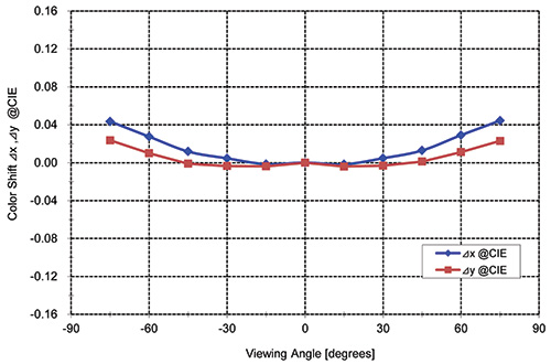
Fig. 3: Color shift is compared to viewing angle.
Power Consumption
Depending on the application, power consumption could be a positive or negative aspect of PMOLED displays. In general, the power usage is directly proportional to the amount of pixels lit. For example, a typical PMOLED display might consume 2 W with 100% “on” pixels, whereas 50% “on” pixels would consume 1 W.
Reliability
PMOLED displays have been certified and tested to meet various automotive OEM conditions.
Special or extreme conditions are evaluated on a case-by-case basis to determine any detrimental results from special test conditions. For example, a typical severe automotive grade test is 85°C/85% RH @ 1k hours and PMOLED displays will not pass this condition/time.
System Interface and Unique Design Applications
PMOLED displays uses a chip-on-glass (COG) graphic-controller driver arrangement with two voltages required in the 8–16 V range plus logic 3.3V. Based on the custom-size-package options and small package footprint, PMOLED displays can be designed into various non-conventional display applications such as control knobs, switches, and other such niche configurations. The ability to add a “corner-cut” in the glass package provides additional packaging options. At this time, a true circular-type display is not available.
Luminance Decay
Luminance decay over the lifetime of the display is a factor for all self-emissive displays.
Ambient temperature is a contributing factor in the slope of this luminance decay, and real-world considerations should be considered in evaluating the relevance of various temperature and lifetime conditions. Some other contributing factors to luminance decay are luminance output and pixel-on time. If luminance requirements can be lowered, lifetime will increase (see Figs. 4 and 5 for 25°C and 85°C luminance decay data).
Differential Aging (Burn-In)
Another aspect of self-emissive-type displays is the tendency to create a “burned-in” image based on different pixel usage rates in the displays. The classic example: a single character displayed for a period of time can still appear as a “ghost” image when the character is no longer displayed and replaced with another character or background (see Figs. 4 and 5 while comparing lit and non-lit pixel areas). One of the negative points of PMOLED displays is this differential aging issue.
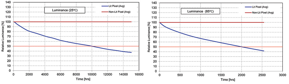
Figs. 4 and 5: Relative luminance is compared against time (25 and 85°C).
Color Shift
Under normal operating time, PMOLED displays can be expected to demonstrate some color shift. This phenomenon can be accelerated under high-temperature conditions (see Figs. 6, 7, 8, and 9 for 25°C and 85°C color-shift data).
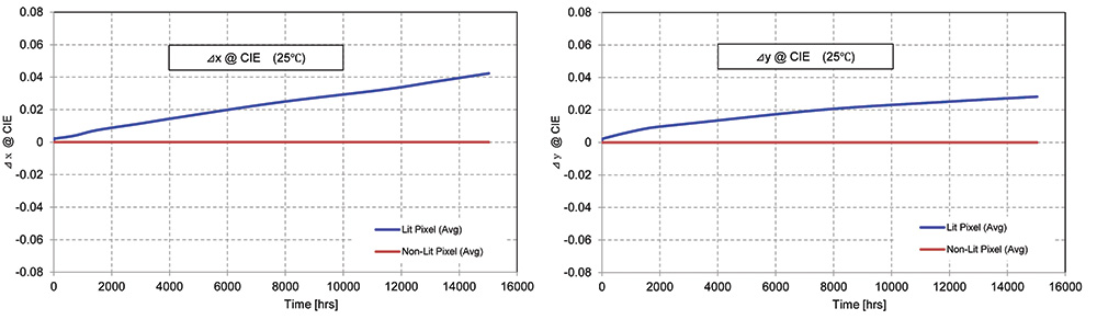
Figs. 6 and 7: Color shift vs. time (25°C) are compared.
Fig. 8: Color shift vs. time (85°C) are compared.
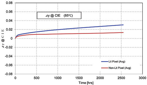
Fig. 9: Color shift vs. time (85°C) are compared.
As with any display technologies, PMOLED displays have their own set of unique pros and cons based on their physical design and structure. PMOLED displays offer the advantages of high contrast ratio, dead-front appearance, wide viewing angle, and slim packaging when compared to some other display technologies. On the other hand, care must be taken to consider the effects of differential aging and color shift/luminance degradation, especially with higher-temperature environments. Consultation with the manufacturer will provide assistance in providing the overall best solution. •
Jeff Hatfield is with Futaba Corporation of America. Akihiro Nonaka and Yoshiyuki Kobayashi are with Futaba Corporation of Japan. They can be reached at jhatfield@ futaba.com, Nonaka@fmd.futaba.co.jp, and KobayashiY@fmd.futaba.co.jp, respectively.