Lasers Improve Display Glass Cutting
Lasers Improve Display Glass Cutting
Non-contact glass cutting by laser offers an attractive alternative to mechanical methods in display fabrication. There are several laser technologies and processing techniques in actual use, each with its own characteristics and advantages.
by Jürgen Serbin and George Oulundsen
Displays for handheld devices, such as smartphones and tablets, increasingly utilize thinner glass, as well as chemically strengthened glass. In addition, screens with curved corners, contoured shapes, and cutouts are becoming more common. These trends make traditional mechanical glass cutting a less-effective method during display fabrication, and a variety
of laser-based techniques have appeared to replace this older technology. This article provides an overview of laser glass-cutting methods and is intended to help readers choose the most appropriate method for a specific application.
Traditional Methods
The traditional technique for cutting glass, used in various forms for centuries, involves scribing the surface of the glass with a hard, sharp tool (typically a diamond or carbide wheel), followed by the application of mechanical stress to propagate the crack completely through the glass. In automated systems, this separation is usually implemented by using a “chopper bar” that descends on the glass.
This method has certain drawbacks, particularly for the aforementioned very thin substrates that are increasingly being employed in flat-panel displays (FPDs). In particular, the mechanical force of the scribing tool produces microcracks in the material, and the subsequent breaking step yields small chips and debris, as well as an edge not necessarily perpendicular to the glass surface. Furthermore, mechanical cutting leaves significant mechanical stress in the finished edge. (In fact, it becomes difficult to use mechanical cutting with substrates below about 1 mm in thickness because the glass is so easily broken.) To prevent further cracking or breaking of the glass after the original cut, it may be necessary to grind or polish the cut surface. Also, a post-process cleaning step may be required to remove debris that could interfere with subsequent processes, such as circuit formation.
For the display manufacturer, various edge-grinding and cleaning steps represent additional production time and costs. They may also have negative environmental impacts, like the generation of debris that cannot be easily disposed of, or large amounts of waste water required for cleaning. In addition, mechanical glass cutting doesn’t readily support the production of curved edges, which are increasingly desirable, especially in FPDs for portable devices.
Laser-Cutting Advantages
There are several different laser technologies currently being used for glass cutting, and these are deployed in a variety of methods. However, all laser glass-cutting techniques offer some similarities in their main benefits.
First, all laser methods are non-contact processes that largely eliminate the problems of microcracking and chipping. Laser-cutting methods minimize residual stress (to varying degrees) in the glass, resulting in higher edge strength. This is critical, because even when force is applied to the center of a glass panel, any break usually initiates at the edge. Consequently, laser-cut glass can typically withstand two to three times as much force as mechanically cut glass.1
Laser cutting can also reduce the number of process steps, since it requires few, if any, subsequent cleaning or grinding stages. So while the capital cost for a laser cutting station is higher than for a mechanical system, the overall investment in laser cutting can be lower than for mechanical processing if an additional grinding machine can be eliminated. The reduced need for post processing and cleaning also makes laser-cutting greener than mechanical methods, and reduces or eliminates the need for water.
Finally, some laser-cutting methods enable the production of curved cuts in glass. The demand for curved cuts is increasing, especially in mobile phones, where many manufacturers would like to produce more complex geometries in their screens, including holes to accommodate buttons, controls, LEDs, and camera lenses. Laser cutting is the only clean and contact-free method to produce these complex curved features. Figure 1 compares mechanically cut and laser-cut glass.
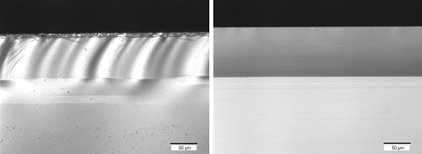
Fig. 1: Above are microscopic views of mechanically cut (left) and laser-cut (right) glass. The mechanically cut glass shows significant residual stress, and substantial debris from the cutting process.
CO2 and CO Lasers
Carbon dioxide (CO2) lasers have been used in glass cutting for many years. In contrast, carbon monoxide (CO) lasers, which were first introduced as practical, industrial tools by Coherent in 2015, are just beginning to be deployed in this application. Both CO2 and CO lasers offer rapid glass cutting and high process throughput. The key improvement, however, is in the differing wavelengths of the CO vs. the CO2 lasers.
The CO2 and CO lasers are infrared sources that process glass by causing intense, local heating. Specifically, all types of glass absorb strongly at the 10.6-µm CO2 laser wavelength, so a focused laser beam causes rapid heating at or near the surface of the glass. To produce a cut, the glass is translated relative to the beam, and either liquid or air is delivered by nozzles onto the glass to quickly cool it. The resulting thermal shock produces a continuous crack. Depending upon the glass thickness, this crack can be propagated all the way through the substrate to complete the cut; this is called full body cutting. Alternatively, for thicker glass, a second step, either laser or mechanical, is used to finish the break; this is called laser scribing (Fig. 2).
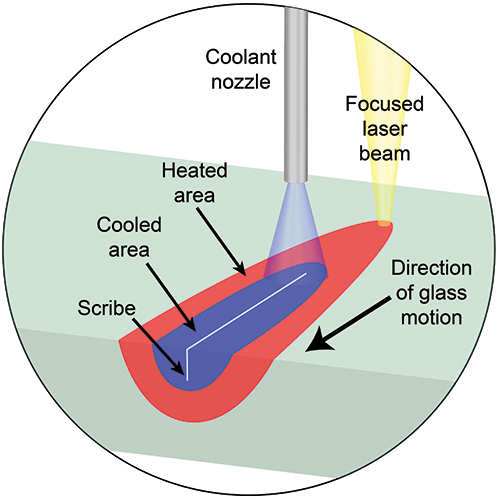
Fig. 2: This schematic illustration of CO2 laser scribing shows the motion of the glass beneath the laser beam.
Because of the high absorption of glass at the 10.6-µm CO2 wavelength, the beam is formed into a long, thin line on the work surface, rather than a circle (which is the way laser beams are most commonly focused). This is necessary in order to adequately distribute the intense heat generated by the laser. However, this geometry means that the glass is always being heated along a line segment, and thus precludes the ability to cut short radius curves.
The overall process is much the same with the CO laser. However, glass absorption of the 5-µm to 6-µm output of the CO laser is significantly lower, allowing the light to penetrate much farther into the bulk material. Thus, heat is introduced to the bulk glass directly and does not rely on diffusion from the surface. Testing at Coherent has shown that this produces even lower residual stress than CO2 cutting, yielding a stronger cut piece, together with a wider process window for the manufacturer.
The other exciting aspect of CO lasers in glass cutting is their ability to support the cutting of curves (Fig. 3). This is because the lower absorption of the CO laser allows its round beam to be used directly without adverse heat effects. In addition, the CO laser can cut chemically strengthened glass.
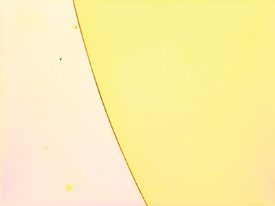
Fig. 3: A CO laser with only 9W of output power produced this clean, curved cut (6-mm radius circle) in thin glass (50-µm thick) at a feed rate of 140 mm per second. This photo (which is not an illustration) shows the laser-cut edge of the piece of glass. The yellow part is the glass, and the face-on view shows the cut.
While CO2 lasers are employed in a very wide range of commercial materials-processing tasks, from cutting thin films for food packaging up to welding thick steel plates, most readers are probably not familiar with CO laser technology. CO lasers were invented decades ago, but never commercialized due to practical considerations involving very limited lifetime and reliability caused by difficulties in cooling the laser. In fact, the first CO lasers required cryogenic cooling, which kept them from being used in any commercial applications. Coherent recently developed new technology that has enabled the manufacturing of sealed CO lasers, which operate at very high output powers, with excellent efficiency at room temperature, and which demonstrate lifetimes in the thousands of hours. Because CO lasers offer distinct advantages for glass cutting, this was one of the first commercial applications pursued for this technology.
Laser Ablation
Laser ablation relies on a completely different mechanism to process glass than do CO2 and CO lasers, which utilize thermal shock to create a crack. Ablation is the actual removal of material, with high precision, to create the scribe. Ablation occurs when laser power is sufficiently high to produce intense local heating (thermal ablation), or at very high peak powers, to directly break interatomic bonds (photo-ablation).
Ablation is accomplished using either solid-state lasers with pulse widths in the nanosecond range, or ultra-short-pulse (USP) lasers with pulse widths in the picosecond, or even femtosecond, range.
There are several different variations on the way laser ablation is used to cut glass, but in all of them, each laser pulse blasts away the glass in the form of microscopic chips. Generally, there is a direct correlation between pulse width and the size of these removed particles. Chips in the single-digit micron size range are produced by nanosecond pulse-width lasers, and USP lasers yield even smaller particles – hundreds of nanometers in size. This process does require cleaning – although the particles produced by the laser are much, much smaller than those produced by mechanical cutting. And the advantage of laser cutting is better edge quality, which directly translates into bend strength.
Nanosecond pulse-width lasers, operating in either the green (532-nm) or ultraviolet (355-nm) bands, usually enter through the top of the transparent substrate and are focused bottom surface to top surface, sequentially. In this so-called “bottom-up” approach, ablated chips fall out of the material interaction zone due to gravity. Scribes or cuts of virtually any edge profile, including tapered slots, holes, trenches, bevels, and chamfers, can be generated by moving the beam focus up through the substrate and then along it to create the desired contour (Fig. 4).
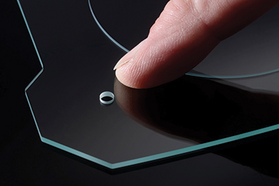
Fig. 4: This example shows a through-hole produced by bottom-up processing in glass.
Processing speeds for this type of ablation are relatively slow compared to other methods. For example, it takes about 1 second to drill a 1-mm diameter hole in 3-mm-thick soda lime glass. The cutting speed for free contours is in the single-digit mm-per-second range. Other drawbacks are that this method cannot process strengthened glass, and the edges typically show significant chipping from about 10 μm to 50 µm from the processed edge.
With USP lasers, scribing is most commonly performed with the laser initially focused on the top surface of the substrate, then the beam focus is adjusted to work down through the material. This is because the very small particles generated don’t readily fall out of the scribe on their own (although there are methods to remove them) and therefore it is challenging to use USP lasers for bottom-up drilling or cutting. In addition to limited cutting speed and some edge roughness, the other limitation of topside scribing using an USP laser is that a taper always remains on the scribe or hole, usually in the 8° to 12° range.
Filamentation Cutting
Glass cutting can also be accomplished through a specific form of internal modification called filamentation, which again utilizes the very high-power densities achieved with focused, USP lasers. In this case, the high laser intensity produces self-focusing of the beam due to the nonlinear Kerr optical effect. This self-focusing further increases power density until, at a certain threshold, a low-density plasma is created inside the material. This plasma lowers the material refractive index in the center of the beam path and causes the beam to defocus. If the beam focusing optics are properly configured, this focusing/defocusing effect can be balanced to repeat periodically and form a stable filament that extends over several millimeters in depth within an optically transparent material. The typical filament diameter is in the range of 0.5 µm to 1 μm. An example appears in (Fig. 5).
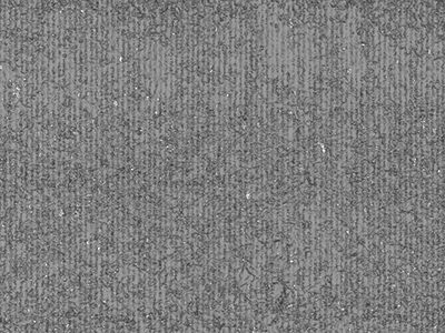
Fig. 5: Laser filamentation creates a series of parallel voids in 0.5-mm-thick sapphire.
In order to achieve effectively zero-gap cutting or perforation lines, these laser-generated filaments are produced close to each other by a relative movement of the work piece with respect to the laser beam. Cutting speeds of 100 mm/s to 2,000 mm/s can be achieved, depending on the material thickness and the desired cut geometry.
Coherent|Rofin’s embodiment of the filamentation technology is called SmartCleave. It pairs process technology acquired and further developed by Rofin, together with advanced industrial USP lasers from Coherent. The resulting process enables high-speed cutting of arbitrary shapes, including curves, freeform cuts, and insets, without taper, into transparent and brittle materials from 0.05-mm to 10-mm thickness (Fig. 6). SmartCleave delivers smooth surfaces, with an average roughness (Ra) of less than 1 μm, which are essentially free of chips and debris. This yields bend strength in the cut parts that is markedly superior to mechanical processes.
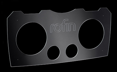
Fig. 6: The SmartCleave filamentation process enables high-speed cutting of curves and insets into glass, e.g., as used for substrates of displays.
With chemically or thermally strengthened glass, internal stress within the part provides for automatic separation of outer contours after the filamentation process, without an additional step. For non-strengthened transparent materials, such as soda lime, borosilicate, and alumino-silicate glass, as well as sapphire, a separation step must follow filamentation. This can be accomplished with a small mechanical or thermal force. For example, the latter can be provided by heating with a CO2 laser.
Coherent|Rofin supplies products to enable this filamentation processing in a variety of integrated configurations. This begins with laser sources, and continues through sub-systems that integrate a laser with beam delivery optics and control electronics. These can also be configured as a so-called “black box” subsystem, in which the particular configuration to enable and optimize a specific process has already been optimized, validated, and programmed.
In conclusion, lasers have proven to be superior to traditional glass-cutting techniques in a wide range of different applications. In general, lasers are most useful when mechanical means fail to deliver the cut quality or characteristics required, or when older methods become too expensive due to the extensive post processing required, or to downstream yield reduction. However, laser glass cutting is actually a broad term covering a variety of different techniques, each with its own unique characteristics and advantages. Thus, it is important to understand the advantages and limitations of each technique and to work with a vendor supporting several techniques in order to choose the optimum one for a specific application.
Reference
1A. Abramova, M. Blacka, and G. Glaesemanna, “Laser separation of chemically strengthened glass,” Physics Procedia 5, 285–290 (2010). •
Jürgen Serbin is product manager for industrial lasers and systems at Rofin and can be reached at J.Serbin@rofin.de. George Oulundsen is director of product marketing at Coherent and can be reached at George.Oulundsen@coherent.com.