A novel pan-tilt user-interface (UI) robot system uses a scanning MEMS projection head in combination with a depth sensor. The UI robot system can detect and track a hand, then project a virtual-remote-controller (VRC) image onto the top of a palm or table.
by Masafumi Ide, Kaoru Yoda, Yosuke Abe, Shinpei Fukaya, Takeo Komiyama, Tomohiro Tamura, Kouhei Arakawa, and Takaaki Nozaki
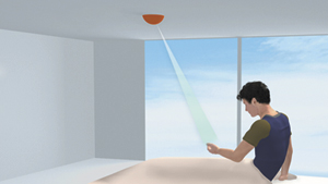
USERS increasingly expect to be able to access and interact with digital information even when they are not sitting in front of a computer. For many applications, the ideal information display would be lightweight and portable. To this end, our research team at Citizen Holdings Co., Ltd., developed a design for a Virtual-Remote-Controller (VRC) system in which a tiny ceiling-mounted laser-projector robot pans and tilts to track a user's hand as the user moves around a room. The robot also projects an image with touch-screen interaction (Fig. 1). Our VRC system was selected by SID's Innovation-Zone (I-Zone) committee as one of the prototypes and new technologies to be shown in the first-ever I-Zone at Display Week 2012 last spring.1,2The system generated a great deal of interest from attendees.
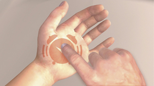
The laser projector has a focus-free feature that helps the projector display icons or images onto the palm of a hand without autofocusing optics. This makes it possible to reduce the size and cost of the projection head unit. Once the operating action disappears via a specific action (e.g., pressing the return button, as in Fig. 1(b), in which a close-up of an alarm-clock image is shown), the VRC system automatically shuts off the projection, and the pan-tilt head returns to a pre-programmed or "home" or "park" position until it senses a hand moving and the process starts over again.
 (a)
(a)
 (b)
(b)
Fig. 1: The Virtual Remote Controller (VRC) system uses a tiny ceiling-mounted laser projector robot (a) that pans and tilts to track a user's hand as he or she moves around a room. (b) The robot projects an image with touch-screen interaction onto the user's hand.
Creating the Laser-Display Infrastructure: Teaming Up with New Applications
Compact visible-range laser modules, including green lasers, have recently become widely available. These modules will be a key factor in creating new markets, especially for mobile or embedded pico-projection systems.3,4 We developed a specific application using this laser technology by focusing on a simple UI system. The system is designed so that a user can access any network or other remote-controlled equipment without smart phones or other electrical equipment.
Previously, other research groups had developed projection-based palm-interface systems using a conventional projector5 or a mobile or wearable projector6,7 with a camera for image processing. Although the fixed-projector approach does not need any moving parts, the accessible area is limited by the size of the projection area, and the system may need to become bigger as a result. In addition, the size of a hand or palm is very small compared to the whole projection area, so the projector uses only a fraction of the output power capability. On the plus side, the mobile- or wearable-projector approach is suitable for pico-projectors, although the user has to carry around the projection equipment.
Our novel UI robot prototype is based on a laser pico-projection system, which can be used as a VRC with hand tracking.8,9 The laser-projection head, mounted on a pan-tilt unit, can be separated from the laser-light-source module by a single-mode optical fiber.10 The system can deliver images of icons or switches for a simple VRC onto a palm or table. Because the projection area can move via a pan-tilt unit, the output power of the projector can be minimized for a small target area only. Consequently, the projection UI robot can be created in a small form factor that can be used with a VRC system in a room or other living space.
Display Generations and Negative-Distance Approach
We propose a new class of display devices, using laser light sources, that are able to find a viewer autonomously and provide useful contextual information. To place the new UI robot system in a larger context, it is useful to review the history of display technologies briefly and to categorize displays as a function of their distance from a viewer.
Each generation of display technology is closely associated with its contents and applications and is constantly changing. Earlier display technologies evolve and flow into later display technologies and vice-versa. Beginning with the invention of large screens for cinema in the 1890s, initial "displays" were designed to be experienced from a long distance. Television broadcast led to CRT developments, including a reduced screen size meant for a reduced distance from the viewer. Then personal computers and Internet access promoted the development of a laptop PC with a flat-panel display and input devices designed for closer use yet. At present, handheld smart phones and tablet PCs with a touch-screen user interface have become dominant. Figure 2 shows a conceptual diagram of the distance between a viewer and a display.
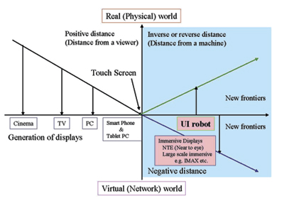
Fig. 2: The distance from a viewer to a display is depicted from farthest distances at left to closest distances at right.
In terms of the distance from a viewer to a display,11 the distance has reached near-zero when we use touch screens and the user is in contact with the display. There are some new frontiers12in "negative distance" regions, in which the viewer can be considered to be "in" the display, or the display in the viewer. Immersive displays should be categorized in these negative distance regions.
There are also similarities among each generation; for instance, a viewer needs to seek and find displays before using them in order to access the information appearing on them. Our team sought to define another negative-distance region relating to the directionality of this seeking activity and to describe the distance from a machine toward a viewer (as opposed to the distance from the viewer toward the machine) as an inverse or reverse distance13 defined by the direction at first contact because the researchers consider the direction from a viewer to the machine as a positive direction.
Projection UI Robot System
Our research team applied an integrated second-harmonic-generation (SHG) laser using a Periodically Poled Lithium Niobate (PPLN) waveguide on a Si platform14 to a green laser (532 nm) for an RGB fiber pigtail module. Figure 3 shows an RGB fiber pigtail module that is integrated with R and B direct lasers (based on TO-38 packages).
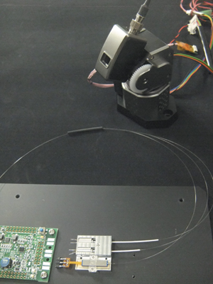
Fig. 3: The robot system's projector head and fiber combiner are at upper right and the RGB fiber pigtail laser module and controller board are at lower left.
Each color output is combined with an RGB fiber combiner and delivered to the scanner head. While one-color lasers or color combinations other than RGB could be used with the UI robot system, RGB's advantages include com-patibility with existing pico-projection engines such as those used in near-to-eye and head-mounted displays. Such compatibility will make it easier to port the robot-system technology to additional applications in the future. Figure 4 shows the structure of the UI robot system, which includes a pan-tilt scanning MEMS projection head connected to a laser source delivered by a single-mode fiber and a depth sensor. The pan range of the MEMS heads is ± 60° and the tilt range is ± 50°.
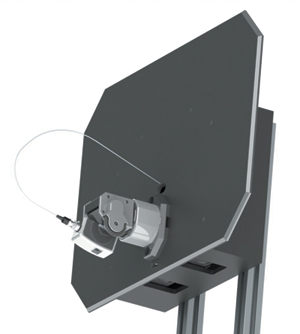
Fig. 4: The projection UI robot system prototype structure includes a pan-tilt scanning MEMS projection head connected to a laser source by a single-mode fiber.
It is possible to achieve the small-form-factor scanner head because of the separation between the light source and the controller boards. The projection head is small enough to embed the scanner head anywhere. The weight of the whole scanner projection head is only 25 g.
Table 1 shows the conceptual comparison between a common pico-projector and a projection UI robot. Both use similar optical engines; however, there are major differences in throw distance, screen size, and resolution.
The differences come from their target applications. Common pico-projectors target high-resolution displays with a small form factor; on the other hand, UI robots are only responsible for interactive virtual icons and other images used for manipulating other equipment.
Table 1: A conceptual comparison between a common pico-projector and a VRC shows differences in throw and viewing distance, among other variables.
| |
Common Picoprojector |
Virtual Remote Controller |
| Throw distance |
Short (0.3–1 m) |
Long (up to 3 m) |
| Viewing distance (from a viewer) |
Medium (1–3 m) |
Short (0.3–0.7 m) |
| Screen (image) size |
Large (e.g., 40-in. diagonal) |
Small (palm top size less than 8 x 8 cm2) |
| Display resolution |
High (more than SVGA) |
Low (QVGA-VGA or less) |
| Device operation |
Handheld (manual operational movement) |
Pan-tilt head (automatic operational movement) |
Applications
We believe that this UI robot system can be used as a ubiquitous and intuitive UI. In order to demonstrate its ability and practicality, we fabricated a prototype of the UI system. For the VRC prototype system employing a UI robot (Fig. 5), we used an ASUS Xtion sensor (ASUS TeK Computer Inc.) as a depth sensor.
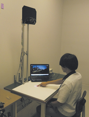
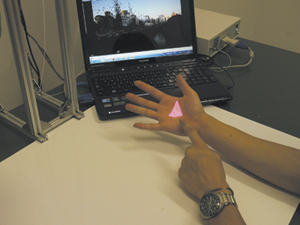
Fig. 5: This VRC prototype shows the projector overhead. The depth sensor works as a motion sensor when the user comes into its field of view. If the user shows some specific gesture for the input mode such as spreading his fingers slightly, as shown in Fig. 6 (a), the scanner head tracks the user's hand using a pan-tilt head and the depth sensor's near-infrared (NIR) image information. When the user presses the virtual image on his palm using his other hand, the VRC can detect the action and remotely control the equipment.
This system can serve one user (or hand) at a time and is deployed on a "first come, first served" basis. In the case of a tabletop system, for instance, a depth sensor tracks a hand; after that, the projection head projects appropriate icon images onto a palm or tabletop. During the operation, the sensor keeps tracking other hands at the same time and places each hand on a waiting list (e.g., up to five). If the first hand performs the exit operation or does not specify any command operation in a given period of time (e.g., 30 sec), the right of operation will be transferred to the next hand on the list. Especially for a palm input mode, a waiting list is effective only if the hand is available from the field of view (FOV) of the depth sensor.
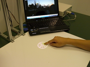
Another form of the VRC is "a tap on table" system. The user can draw the virtual switch on the tabletop by a double tap. The user can also operate some functions such as the fast-forward, fast-rewind, and volume-control buttons on a Windows media player via the VRC [Fig. 6(b)].
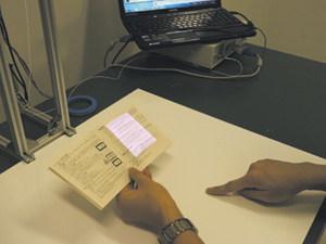
The UI robot system can also be applied to a lighting robot system. In this case, the light from the projection system is used as lighting with a virtual remote controller and object-tracking feature. The brightness or direction of the light is adjusted by the virtual controller. The selected projection or lighting area for the object [e.g., a book in Fig. 6(c)] can be followed by the pan-tilt head of the UI robot.
 (a)
(a)
 (b)
(b)
 (c)
(c)
Fig. 6: One possible application (a) uses a virtual control image on the palm of a user's hand. Other possibilities are a tabletop icon (b) and a lighting area for an object such as a book (c).
Ultimate Applications
Our team has proposed a new class of display applications in conjunction with a VRC system using a UI robot prototype that employs a MEMS-based pan-tilt laser projection head in combination with a hand-tracking sensor. Many of these applications are for home or office use. We also believe that this VRC system using the UI robot can be effective in public spaces such as hospitals, for instance, where it might help prevent the spread of infectious diseases that are transmitted through touch. This novel class of display technology should open the door to new laser projector-based applications and hence to many new user experiences.
Acknowledgments
Our thanks to Mr. Yoshinaga and Mr. Noda from Reliable System Supply, Ltd., for helping us to prototype a VRC system.
References
1Pan-Tilt Projection UI Robot using a Fiber Pigtailed RGB Laser Light Source live demonstration by Citizen Holdings at Display Week 2012, I-Zone exhibition (Boston, MA, USA, June 2012).
2A. Poor, http://idmagazinedisplayweek2012.blogspot.jp/2012/06/i-zone-rocks.html.
3R. B.Sprague, T. Montague, and D. Brown, "Bi-axial Magnetic Drive for Scanned Beam Display Mirrors," Proc. SPIE 5721, 1–13 (January 2005).
4B. T. Schowengerdt, H. G. Hoffman, C. M. Lee, C. D. Melville, and E. J. Seibel, "Near-to-Eye Display using Scanning Fiber Display Engine," SID Symposium Digest 41, 848–851 (May 2010).
5Y. Ishii, M. Kobayashi, M. Nakashige, and H. Koike, "Palm Interface: A Display Personally to Show Information in Public Spaces by using Image Processing," Trans. IPS Japan 49(7), 2528–2538 (2008) (in Japanese).
6P. Mistry, P. Maes, and L. Chang, "WUW-wear Ur world: a wearable gestural interface," Proc. CHI EA '09, 4111–4116 (2009).
7G. Yamamoto and K. Sato, "PALMbit: A Body Interface Utilizing Light Projection onto Palms," Journal of the Institute of Image Information and Television Engineers 61, 797–804 (2007) (in Japanese).
8Y. Abe, T. Komiyama, T. Nozaki, M. Ide, Y. Noda, and A. Yoshinaga, "Virtual Remote Control System using a Fiber Pigtail Scanner Head," Proc. Optics & Photonics Japan 2011(OPJ 2011), 30aH1 (November 2011) (in Japanese).
9Virtual Remote Controller Prototype by Citizen Holdings (booth No. L1007) at the Photonics Festival in Taiwan 2011 exhibition (Taipei, Taiwan, June 2011).
10S. Katoh, M. Ide, T. Takeishi, and T. Nozaki, "Liquid Crystal Circular Polarization Switching Device for 3D Laser Pico-projectors," Proc. Laser Display Conference 2012 (LDC 2012), LDC2-3 (April 2012).
11E. F. Kelley, "Resolving Resolution," Information Display 27, 9 (2011).
12M. Ide, "Next generation displays using laser light sources," presented at the 8th LDT research group meeting (April 2011) (in Japanese).
13B. T. Schowengerdt, Department of Mechanical Engineering, University of Washington, Seattle, WA, USA (personal communication, June 2012).
14S. Fukaya, K. Yoda, T. Nozaki, and M. Ide, "Flat Fiber Pigtailed SHG-Green Laser Module Integrated on a Si Platform," Proc. Laser Display Conference 2012 (LDC 2012), LDC p7–9 (April 2012). •