Binocular Fusion Camera Enables Photography of 3-D Displays for Evaluation Purposes
The binocular fusion camera is a simple apparatus that permits a user to see what is on the screen so that the eyes can converge to create 3-D imagery. Left- and right-eye images can be overlapped to render how 3-D images will appear to both eyes, or the images can be rendered above and below each other in order to make motion artifacts visible. With this valuable tool, new insights into the visual performance of 3-D displays can be achieved.
by Edward F. Kelley and Paul A. Boynton
WHEN we look at a stereoscopic three-dimensional (3-D) display that requires glasses, but without using the glasses, the overlapping images are hard to interpret. It is sometimes helpful to put the images that can be seen by each eye into a single image representing the view of two separated eyes. Conversely, for examining motion artifacts, such as created by the motion of a small box across the screen, it is useful to separate the images of the box above and below to see how each eye image changes in time. The authors therefore created an apparatus that permits either the blending or separating of the view from each position of the eye onto a single detector or camera.1 The apparatus has an interocular distance of 65 mm so that it can use the normal 3-D glasses that accompany many 3-D displays or it can be used with autostereoscopic displays without glasses.
A schematic of the binocular-fusion (BF) camera apparatus is shown in Fig. 1. There are two versions. When there is a single detector such as a lensless camera pixel array, photodiode, or photomultiplier tube upon which one wishes to place the left and right images together, lenses are employed at the front of the device. Irises adjustable from 1 to 12 mm in diameter are mounted in front of coated 300-mm focal-length achromatic lenses. The irises permit changing the effective resolution of the camera should it be desirable to simulate the resolution of the eye. These iris–lens combinations and elliptical mirrors (25-mm minor axis) oriented at 45° are mounted on small rails that can be rotated by manual positioners in order to simulate the vergence of the eyes. Those mirror mounts have differential adjusters that are indispensable in providing very fine control of the position of the left and right images.
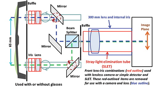
Fig. 1: A schematic layout of a binocular-fusion camera shows configurations for both a lensless camera/detector and a camera with a lens.
By using a second non-adjustable elliptical mirror positioned at 45° in the center, the image of the right eye is directed straight through a 25-mm non-polarizing 50:50 beam splitter into the detector or camera. The left-eye image is directed into the side of the beam splitter and reflected into the detector or camera. This arrangement is used so that the left and right image paths have the same length. A front baffle must be provided to prevent leakage of the light from the display bypassing the optics into the detector. A second baffle is placed at the output of the beam splitter to further prevent stray light and other scattering problems from the optical components (see Fig. 2).2
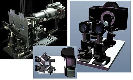
Fig. 2: The photograph of the binocular-fusion camera (top left) shows the configuration with a single lens on the camera. The graphical images above and at top right show the use of a camera body and frontal lens-iris combinations without baffles or SLET.
The configuration in Fig. 1 that uses a 300-mm focal-length lens on the camera instead of the front lenses and irises is probably the easiest configuration to use because both eye paths employ the same lens and iris that is on the camera. The reason for the long-focal-length lenses in either configuration is so that the pixel information can be resolved as well as being able to have the long paths through the apparatus where the observation or viewing distance is approximately 2 m.
The alignment of the BFC is the most difficult part of using the camera. By removing the camera (or front lens–iris components) and looking at a target with markings at 65 mm placed at the measurement distance, it is possible to use one’s eyes to align the markings for infinity viewing. However, this is only a very coarse alignment. Putting the camera back in place and looking at a 3-D display with horizontally separated objects will require much finer adjustments. The tilt of the beam splitter can greatly affect the alignment at the magnifications sufficient to resolve individual pixels.
Application Examples
One use of the BF camera is to record how a stereoscopic image might be binocularly fused by removing the horizontal separation of the left and right images to simulate what would be seen with both eyes.
Figure 3 shows a frame from a popular computer-animated movie, the enlarged image of the
right eye in the image (left to the viewer), and the BF camera image of the 3-D result.3 The images are taken from a film-patterned-retarder (FPR) 3-D display where the odd lines are seen by the left eye and the even lines by the right eye.
For the fused image to represent what the eye sees, recall that it is necessary for the viewer to be a sufficient distance from a FPR display, usually 3.2 screen heights or farther for 20/20 vision acuity.4 There are two ways to align the left and right images for the FPR display: (1) vertical alignment of the pixels or (2) alignment of the contours of the edges of objects. We would suspect that the eye would align the contours and not the pixels. The bottom BF camera image in Fig. 3 has the pixels vertically aligned at the highlight. The resulting fused image shows excellent rendering of the 3-D image where each line is different and representative of 1080p vertical resolution.
Is this what the eyes see? No, the eyes see better than this. Note that in Fig. 3 some of the edges away from the highlight are ragged. This can be because those parts of the image are not in the same plane as the highlight. When the eye sees other parts of the image, it quickly fuses the two images properly, making the contours smooth. Thus the BF camera is really only good for fusing the two-eye images at a single plane of the object being studied if that object spans a range of depths in the 3-D image. Some of the ragged edges in the image in Fig. 3 also arise because of different exposures for the left and right lines owing to imperfections in the BF camera and a slight coloration difference from the beam splitter. It is very difficult to properly tilt the beam splitter to assure accurate pixel alignment across the entire image.
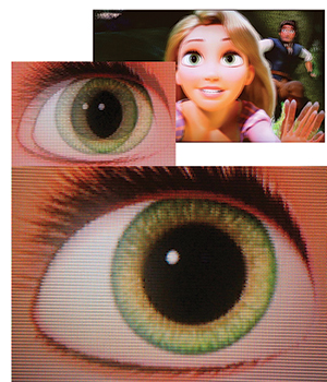
Fig. 3: This frame from the movie Tangled shows an apparent face image in front of the screen surface on a film-patterned-retarder 3-D display. The binocular-fusion camera can attempt to align the separated left and right images of the character’s eye to binocularly fuse the images together. The highlight on the cornea was used to establish the plane of alignment. Parts of the image at different depths show misalignment and ragged edges.
The BF camera can separate the images of the left and right eyes as well as combine them. It is interesting to investigate whether the motion artifacts are different for left and right eye images on a 3-D display; for example, if a white box could be moved horizontally across a black background on the display at a specified
pixel increment for each frame. Here, the authors used the side-by-side mode of the 3-D display with the motion increment of four pixels in the original moving pattern, resulting in an 8 pixel per frame movement in the side-by-side 3-D image. Using a high-speed camera and a FPR 3-D display, the horizontal motion of that
small block can be recorded for both eye images at the same time. Figure 4 shows (a) the high-speed camera in use with the binocular-fusion optics, (b) the pattern on the screen with stationary small vertical lines in addition to the moving boxes, and (c) one sequence of the 10 × 50 moving white box against a black background with the right image oriented directly above the left image.
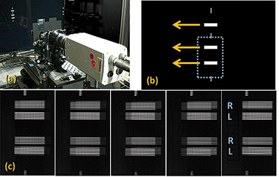
Fig. 4: In (a), the high-speed camera is shown in use with the binocular-fusion optics. In (b), the pattern on the screen with stationary small vertical lines appears in addition to the moving boxes. In (c), one sequence of the 10 x 50 moving white box against a black background is depicted with the right image oriented directly above the left image. Almost one display frame is shown in (c), where the interval between images is 4 msec, making a 16-msec total duration.
Almost one display frame is shown in (c) where the interval between images is 4 msec, making 16-msec total duration; the original high-speed sequence is captured at 1000 camera frames per second. (To see all the processes going on, such as a rolling backlight, the authors generally use from 10,000 to 15,000 frames per second.) The resulting image sequence can be analyzed according to standard methods to determine moving-edge blur profiles.5
Uses of the BFC
What the binocular-fusion camera provides is a means to document what is on the display surface of a 3-D display whenever the overlapping left and right images
are difficult to interpret with normal 2-D photography. If the left and right images of any object are in the plane of the screen, then we can use normal 2-D photography to capture what is on the screen because both left and right images are aligned when the object is in the plane of the screen. However, when any object is not in the plane of the screen, then we can use the BF camera to fuse and photograph the left and right images together to simulate what the eyes will see when
looking at the object through 3-D glasses. We can also separate the left and right images to examine motion artifacts created by moving objects. In all this, the objective is to use the binocular-fusion camera to help document how a 3-D display is performing with the presentation of either static or moving 3-D images.
References and Comments
1E. F. Kelley and P. A. Boynton, “Binocular Fusion Camera to Render Pixel Detail in 3D Displays,” SID Symposium Digest of Technical Papers 43, Paper 12.5L, 145-148 (2012).
2Certain commercial equipment, instruments, materials, systems, and trade names are photographically identified in this paper in order to specify or identify
technologies adequately. Such identification is not intended to imply recommendation or endorsement by the National Institute of Standards and Technology, nor is it intended to imply that the systems or products identified are necessarily the best available for the purpose.
3Tangled by Walt Disney Animation Studios, distributed by Walt Disney Studios Motion Pictures, © 2010 Disney Enterprises, Inc. This is a Blu-ray® 3D movie. We use frame 15 at time 1:00:05 of scene 8 (of 13); this is where Rapunzel is saying “easy.”
4E. F. Kelley, “Resolving Resolution,” Information Display 27, No. 9, 18–21 (2011).
5Information Display Measurements Standard, 12.3.3 Moving-Edge Blur from Digital Pursuit, of the International Committee for Display Metrology of the Society for Information Display, Ver. 1.03 (June 2012). •
Ed Kelley is a consulting physicist with his own small, one-man company, KELTEK, LLC, and a private laboratory. He can be reached at ed@keltekresearch.com. Paul Boynton is an electrical engineer with the Applied Electrical Metrology Group of the Physical Measurement Laboratory of NIST.