Light-Field Imaging and Display Systems
Light-Field Imaging and Display Systems
Light-Field Imaging and Display Systems
Light-field imaging and display are often treated as separate areas, but at a conceptual level they are closely related. Display can be viewed as the reverse path of imaging, and this way of thinking can be helpful in the design of either type of system. This article offers a brief outline of both light-field imaging and display systems and a roadmap for their practical use going forward.
by Nikhil Balram and Ivana Tošić
THE light field is an old concept that has become increasingly relevant in recent times because of the advances made in digital and optical technologies and an improved understanding of how the human visual system perceives and interprets the world. This article provides a brief introduction to the concept and an overview of how light fields are captured (imaged) and displayed. Light-field imaging and display are often treated as separate areas because the approach, rigor of the design process, and clarity of possible applications and value propositions are quite different, with imaging being much further advanced in some respects. At the same time, at a conceptual level, one can view a light-field display as the reverse path of light-field imaging, and this way of thinking can be helpful in the design of either type of system, when practical tradeoffs and limits have to be contemplated.
Introduction to Light Fields
Unlike a photograph that represents visual information as a projection of light on a 2D image plane, a light field represents the world around us through a set
of light rays that fill up the 3D space. Even though not formally called the “light field,” this concept dates back to the beginning of the 16th century and to Leonardo da Vinci, who referred to these sets of rays as “radiant pyramids.” The introduction of the term “light fields” came four centuries later, in 1936 when Arun Gershun defined the light field as the amount of light traveling in every direction through every point in space. In 1991, Adelson and Bergen1 formally defined the seven-dimensional “plenoptic function” to represent the visible radiance emanating from every object in the world to the human eye (Fig. 1, left image). This function is parametrized by the three-dimensional co-ordinates of the viewer (camera), the two dimensions (angular or cartesian) of the view direction, the wavelength, and the time. This function offers a complete representation of the light in a scene, but is too high dimensional to be of practical use. However, subsets of it can be used to represent and extract information.
The subset that provides the most generally useful representation for imaging and display is the 4D light field. The parametrization most commonly used today comes from Levoy and Hanrahan,2 who represented the 4D light field as the coordinates of the two intersection points that any ray would have with two parallel planes (see Fig. 1, right image), producing a spatio-angular representation L(u,v,s,t), with two dimensions (u,v) that are angular and two (s,t) that are spatial.
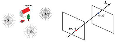
Fig. 1: The plenoptic function represents all the radiance in the world (left). The 4D light field can be defined by the intersection of a ray with two parallel planes (right). (Information Display, Nov/Dec 2014)
Light-Field Imaging
The light field contains a wealth of useful information that can be acquired in its entirety or extracted in the form of application-specific subsets. Two fundamental approaches for acquisition of the light field use a two-dimensional array of synchronized cameras or a single camera with a two-dimensional array of microlenses between the main lens and the image sensor (see Figs. 2 and 3).
The early approaches to light-field acquisition used the concept of a camera array, either created temporally by moving a single camera2 for static imaging or more generally with a physical N × N array.3 The camera array approach provides high spatial resolution (since each camera has a K × K sensor, where K could be a large number), good image quality, and a broad range of distances at which object depths can be resolved (by constructing an appropriately wide baseline between the left/top versus the right/bottom views). The disadvantages are the significant bulk of the system, the difficulty in synchronizing and calibrating across many separate cameras, and the limited view resolution (since there is a physical limit to how closely together the cameras can be placed).
Subsequent approaches to light-field acquisition focused on a compact single camera that uses a K × K array of microlenses placed in between the image sensor and main lens of a conventional camera; an example of this approach is described in a 2005 Technical Report CSTR.4 The microlens array (MLA) can be placed at different positions between the main lens and image sensor, but the most common and (computationally) convenient approach places the MLA at the focal plane of the main lens and the image sensor at the focal plane of the MLA. This results in the capturing of N × N views by the corresponding sensor elements under each microlens, and these sub-images can be processed to produce a set of N × N images in which each represents a unique view with a spatial resolution of K x K (see illustration in Fig. 4). This approach provides the advantages of a convenient portable form factor, high density of views (since N can be made reasonably large for a high-resolution image sensor), and the added option of capturing multi-spectral content by inserting a multi-spectral filter in front of the main lens.5 The disadvantages are the reduced spatial resolution (which is defined by K, the number of elements in each dimension of the MLA), and the very small baseline between the left/top and right/bottom views, which limits depth imaging to nearby objects.
The camera-array approach was primarily used in research between 1995 and 2005, while various vertical application solutions were developed based on the single
camera with the MLA approach, with, for example, Lytro introducing a consumer camera in 2011 and Raytrix and Ricoh introducing industrial cameras in 2010 and
2014, respectively (see Fig. 2). However, the recent resurgence of interest in consumer virtual-reality (VR) HMDs has motivated the development of spherical camera arrays as a means of capturing the 360° light field and processing it to provide cinematic VR content - see the examples of Jaunt ONE and Lytro Immerge in Fig. 2.
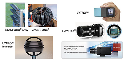
Fig. 2: Light-field imaging can use an array of cameras arranged in a rectangular or spherical configuration (left) or a compact single camera that uses a microlens array (right).
Figure 3 shows the duality between the camera array and the MLA + sensor approaches. It is interesting to note the reversal that occurs between the roles of the N × N and K × K parameters. A similar type of duality exists in the case of fundamental light-field-display architectures, where the camera array is replaced by an array of displays such as projectors or microdisplays, and the MLA + sensor is replaced by the MLA + display.
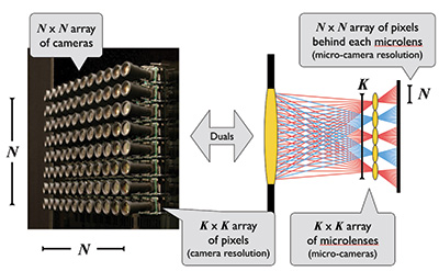
Fig. 3: Depicted above is the duality between the array-of-cameras approach (left) and the single-camera-with-microlens-array approach (right) (Information Display, Nov/Dec 2015).6
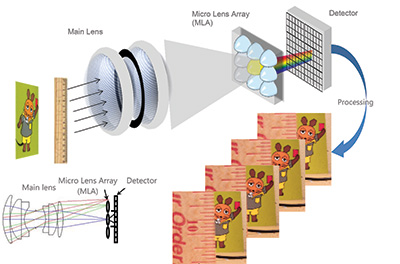
Fig. 4: The light-field camera architecture includes the main lens, microlens array, and detector (sensor). The raw image has to be processed to produce sub-images representing the different views.
As shown in Fig. 5, a robust system design methodology is used to design light-field imaging systems that are optimized for specific vertical applications; for example, as described in a 2013 paper by Berkner et al.7 The major elements of the system are modeled and optimized through the use of performance metrics that are specific for each application. For example, in the case of a color inspection camera, the performance metric is the error between the computed and known chromatic properties of a color calibration pattern.
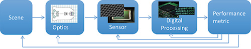
Fig. 5: In a system design model for light-field imaging, each major element of the system is modeled and the appropriate performance metric is chosen for each specific application. An iterative optimization process is used to design the optimal system for that application.7
The most important components of light-field imaging systems are:
• Calibration
• 3D (depth) estimation
• Resolution enhancementa
• Multi-spectral image processingb
We will briefly discuss the first three here. More detail can be found in the references.
Calibration: This refers to the process of taking raw data acquired by the sensor and converting it into a 4D (u,v,s,t) light-field representation. This involves a number of steps.8 The first step, which has to be done only once for a given camera instance, includes locating lenslet image centers by using a white test image, estimating grid parameters, and building and saving the lenslet grid model. The additional steps, which have to be done for each acquired image, include some or all of the following: demosaicing to fill in complete R, G, B values from the Bayer pattern data; correcting vignetting by normalizing with the white image; resampling the image onto an integer grid using 1D or 2D interpolation; converting the grid from hexagonal to orthogonal (if hexagonal MLA is used); and slicing the results into a 4D light field L(i,j,k,l) where (k,l) are the coordinates of each superpixel (representing one spatial point) and (i,j) are coordinates representing points (views) inside each superpixel. Thereafter, a system model needs to be estimated to allow conversion from homogenous coordinates to ray space coordinates (u,v,s,t), including adjustment for distortions in the real system.
3D (depth) estimation: This refers to the process of estimating the depth of a scene. Depending on the needs of the specific application, a generative model can be used to estimate the depth of planar scene layers9 or, alternatively, a dense depth estimation approach can be used to assign depth to each spatial position10,11 (see Fig. 6).
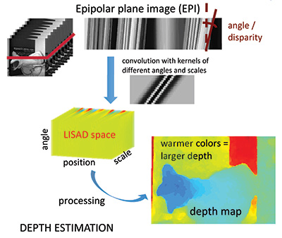
Fig. 6: A 3D estimation (dense depth-map generation) process using the LISAD approach.10
The latter uses 2D light-field slices called epipolar plane images (EPIs) that have one spatial and one angular dimension. Each EPI contains linear structures called “rays” that represent the radiance properties of a spatial point viewed from different angles. Points that lie on the focal plane of the main lens have negligible shifts across views and form vertical rays, whereas those that are in front or behind the focal plane show significant deviation and form slanted rays. Consequently, the angle of a ray provides information about the depth of the corresponding point. In 2014, Tošić et al.10 identified rays and their angles by localizing extrema in a novel scale-depth space representation of light fields, called LISAD (Light Field Scale And Depth), which is built upon the first and second derivatives of a Ray Gaussian kernel. Rays and their angles were further combined and processed to develop a dense depth map of a given 3D scene.
Enhanced resolution: Spatial resolution is a challenge for plenoptic systems because they trade it off to obtain a mixture of spatial and angular information. Higher resolution can be obtained physically by reducing the microlens diameter (and corresponding sensor pitch) and increasing the number of microlenses in the array or by increasing the sensor size to allow more micro-lenses of the same diameter. Either approach has tradeoffs – the former runs into diffraction limits and sensor noise issues; the latter makes the system larger and more expensive.
Resolution can also be increased algorithmically by using advanced super-resolution algorithms, but these provide limited improvements with the simple plenoptic architecture that is commonly used. A different architecture, sometimes called “focused plenoptic,”12 that moves the MLA out of the focal plane of the main lens, thereby spreading rays from each object into adjacent superpixels, enables the use of super-resolution algorithms to provide significantly higher resolution, but at the cost of reduced angular resolution and additional complexity.
Figure 2 shows some prominent examples of light-field imaging systems currently being
used in various vertical applications. We can expect a lot more systems to join this list in future.
Light-Field Displays
Light-field displays offer the promise of displaying realistic three-dimensional content in a way that appears natural to the human visual system. By applying the Turing test to displays, the ultimate goal would be a display that looks like a window through which the real world is visible. If a light field represents the radiance in a real scene that is visible to the human eye, then a display that provides a light field should create the same sensation and satisfy a Turing-like test. The display should provide the same type of depth cues that the human visual system gets from the real world. Most of these cues are monocular, falling into the categories of geometry, color, and focus, and are satisfied by properly captured or synthesized 2D images and video.
The two major binocular cues are vergence and retinal disparity. These can be provided by simple stereoscopic 3D systems that use single or dual 2D screens to show left- and right-eye images that are appropriately shifted according to their desired depth placement. But a fundamental, and now well known, problem occurs because of the coupling between the binocular cue of vergence (the two eyes rotating appropriately to make their lines of sight intersect at the 3D point at which the viewed object is placed) and the monocular cue of accommodation (the lens of each eye adjusting to focus on the same 3D point). This strong coupling is broken by the unnatural presentation of 3D content on a single display plane. Studies by researchers such as Banks et al.13 have shown the significant discomfort and viewing problems caused by this cue conflict.
In order to offer natural viewing of 3D content, light-field displays can be used to create an accommodation response that is consistent with the vergence cues. Fundamentally, there are two ways of doing this: (i) the integral-imaging approach – creating parallax across each eye that produces the correct retinal blur
corresponding to the 3D location of the object being viewed – by presenting multiple views per eye and (ii) multi-focal-plane approach – physically placing the object at the appropriate focal plane corresponding to its 3D location – by providing multiple focal planes. All real light-field displays use one of these two approaches.
The integral-imaging approach is the reverse path of the light-field imaging architectures we saw in Fig. 3 in the previous section. The same analogy of the array of cameras with each having its own sensor versus the array of micro-lenses sharing a single sensor applies here (but with light going in the reverse direction) – with the display equivalent of the former being an array of projectors or
microdisplays and of the latter being a display with an array of micro-lenses on top of it. In either case, a natural accommodation response is created by providing correct retinal blur. Super multi-view (SMV) displays aim to provide a natural focus cue by providing at least two views to each eye. The rationale for two views being sufficient is based on the simple trigonometric construction shown in Fig. 7 developed by Takaki et al.14,15
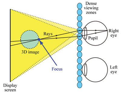
Fig. 7: Shown is a basic system model for a Super-Multi-View (SMV) display.15
However, it is not clear how sensitive this two-view minimum is to viewing distance or whether it creates retinal blur that can provide appropriate size and distance cues. It is likely that a larger number of views per eye are needed and the true minimum number that provides natural retinal blur is not known yet, although
there has been some work in modeling of parallax-barrier-based light-field displays16 that suggests how a theoretical foundation could be developed to answer this question. There is a clear need for further user studies on this topic.
The multi-focal-plane approach is a practical approximation of a light-field display that only works for a single viewpoint at a time. Spatial or temporal multiplexing can be used to create multiple focal planes that place objects at appropriate distances to be consistent with vergence. Akeley17 built a three-plane system using spatial multiplexing of a single high-resolution display and demonstrated that it could provide consistent vergence and accommodation cues that enabled comfortable viewing of 3D content. He showed that depth-weighted linear inter-polation could be used to place objects in between the display planes, and his work suggests that 16 or fewer planes might be sufficient to provide an appearance of continuous depth. Schowengerdt et al.,18 Llull et al.,19 and others have used temporal multiplexing instead to produce the effect of
multiple planes. Figure 8 shows the spatial and temporal approaches used by Akeley and Llull et al., respectively, and the linear interpolation used to provide continuous depth in between the planes.
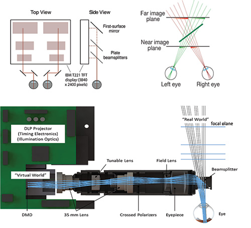
Fig. 8: The multi-focal display systems shown above use spatial multiplexing (top left)13 and temporal multiplexing (bottom image shows one eye; system is duplicated for two eyes).19 Depth-weighted interpolation is used to produce a perception of continuous depth across the discrete planes (top right).
More sophisticated and higher-performing depth-value generation approaches based on non-linear optimization of functions that consider the content and the
visual system response have been developed recently.20–22 As is often the case, there is a tradeoff between image quality and computational requirements.
Light-field displays can be divided into two different types based on fundamentally different use cases: group/multi-user displays and personal (near-to-eye/head-mounted) displays. Group displays are discussed briefly in this paper, while head-mounted displays for VR and AR are the subject of the article by Hong Hua that also appears in this issue.
Three major types of group/multi-user displays include scanning, multi-projector, and multi-layer. The first two are discussed in detail in Liu’s overview paper,23 and the third is discussed in articles such as one by Wetzstein24 published in 2015.
The scanning type of group light-field displays uses a very high-frame-rate projector (usually DLP) with a rotating directional diffuser screen that could be transmissive or reflective (see Fig. 9).
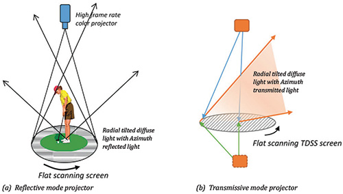
Fig. 9: This group light-field display uses the scanning type of approach with a high-frame-rate projector – using reflective diffuser screen (left) or transmissive diffuser screen (right)23 (Information Display, Nov/Dec 2014).
Multi-projector systems use a tightly packed 2D array of projectors and a vertical diffuser screen to provide a light field with horizontal parallax F(see ig. 10).23
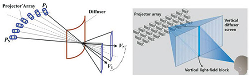
Fig. 10: This group light-field display uses a multi-projector array approach with a vertical diffuser screen that provides horizontal parallax only.23 (Information Display, Nov/Dec 2014.)
Multi-layer displays comprise a stack of programmable light modulators and refractive optical elements. The concept started over a century ago with the use of parallax barriers (Ives 1901) and lenslets (Lipmann 1908) and has expanded to the concept of an active stack using spatially and temporally modulated LCD panels and possibly a directional backlight based on a lenslet array (see Fig. 11).

Fig. 11: This group light-field display uses a multi-layer approach – a compressive display employing a stack of LCD panels with directional (left side) or regular backlight.25 A directional backlight is created by using a lenticular lens array on top of the bottom LCD panel, as shown on the left side of the figure.
In our opinion, because of the significant tradeoffs and system costs, group/multi-user light-field displays are likely to be focused on specific narrow vertical market applications such as museums, simulators, and high-end demo and conference rooms for the next several years and mainstream consumer usage (as replacements for TVs) will not occur before 2020. However, it is possible that high-resolution autostereoscopic TVs using Super-Multi-View could be marketed as “Light Field TVs,” similar to the way LCD TVs with LED backlights have been marketed as “LED TVs.”
On the other hand, single-user (personal) displays mounted on one’s head significantly reduce the system requirements because they only need to present a high-quality viewpoint to one user. This reduction allows for practical architectures such as a multi-focal-plane21 and dual-stack compressive16 to be used for AR and VR, respectively. Such displays used for augmented or virtual reality can provide many types of compelling user experiences and are likely to see adoption in vertical market applications and broader consumer segments such as entertainment, gaming, and education within the next 5 years.24,27 Since the quality of user experience will be of paramount importance in the successful and widespread adoption of these systems, light-field displays are likely to play a major role. For this reason, the next article in this issue, written by Hong Hua, is focused on recent advances in light-field displays for VR and AR HMDs.
Acknowledgments
Stanford is a registered trademark of Stanford University. The Lytro and the Lytro logo are trademarks of Lytro, Inc., registered in multiple countries. Raytrix and the Raytrix logo are registered trademarks of the Raytrix GmbH. Jaunt ONE is a registered trademark of Jaunt, Inc.
References
1E. H. Adelson and J. R. Bergen, “The plenoptic function and the elements of early vision,” Computational Models of Visual Proc. (MIT Press, 1991).
2M. Levoy and P. Hanrahan, “Light field rendering,” SIGGRAPH 1996.
3B. Wilburn, M. Smulski, H. K. Lee, and M. Horowitz, “The Light Field Video Camera,” Proc. Media Processors, SPIE Electronic Imaging (2002).
4R. Ng, M. Levoy, M. Bredif, and G. Duval, “Light field photography with a handheld plenoptic camera,” Technical Report CSTR (2005).
5R. Horstmeyer, G. Euliss, R. Athale, and M. Levoy, “Flexible multimodal camera with light field architecture,” IEEE International Conference on Computational Photography, 2009.
6K. Akeley, “Light-field imaging approaches commercial viability,” Information Display 6, No. 15 (Nov./Dec. 2015).
7K. Berkner, L. Meng, S. A. Shroff, and I. Tošić, “Understanding the design space of a plenoptic camera through an end-to-end
system model,” OSA Applied Imaging Congress (June 2013).
8D. G. Dansereau, O. Pizarro, and S. B. Williams, “Decoding, calibration and rectification for lenselet-based plenoptic cameras,” CVPR (2013).
9Y. Lin, I. Tošić, and K. Berkner, “Occlusion-aware layered scene recovery from light fields,” Proceedings of IEEE ICIP (2013).
10I. Tošić and K. Berkner, “Light field scale-depth space transform for dense depth estimation,” CVPR Workshops (June 2014).
11I. Tošić and K. Berkner, “3D Keypoint Detection by Light Field Scale-Depth Space Analysis,” ICIP (October 2014).
12T. Georgiev, “The focused plenoptic camera,” http://www.tgeorgiev.net/EG10/Focused.pdf.
13M. S. Banks, K. Akeley, D. M. Hoffman, and A. R. Girshick, “Conflicting focus cues in stereoscopic displays,” Information Display (July 2008).
14Y. Takaki, “High-density directional display for generating natural three-dimensional images,” Proc. IEEE 94, 3 (2006).
15Y. Takaki, K. Tanaka, and J. Nakamura, “Super multi-view display with a lower resolution flat-panel display,” Opt. Express 19, 5 (Feb. 2011).
16F. C. Huang, G. Wetzstein, B. Barsky, and R. Rasker, “Eyeglasses-free display: towards correcting visual aberrations with
computational light field displays,” SIGGRAPH 2014.
17K. Akeley, “Achieving near-correct focus cues using multiple image planes,” Ph.D. thesis (Stanford University, 2004).
18B. T. Schowengerdt and E. J. Seibel, “True Three-Dimensional Displays that Allow Viewers to Dynamically Shift Accommodation, Bringing Objects Displayed at Different Viewing Distances Into and Out of Focus,” Cyperpsychology & Behavior (2004).
19P. Llull, N. Bedard, W. Wu, I. Tošić, K. Berkner, and N. Balram, “Design and optimization of a near-eye multi-focal display system for augmented reality,” COSI (June 2015).
20R. Narain, R. A. Albert, A. Bulbul, G. J. Ward, M. S. Banks, and J. F. O. Brien, “Optimal presentation of imagery with focus cues on multi-plane displays,” ACM Trans. Graphics 34, No. 4 (August 2015).
21W. Wu, I. Tošić, N. Bedard, P. Llull, K. Berkner, and N. Balram, “Near-eye display of light fields,” IDW 2015.
22W. Wu, I. Tošić, N. Bedard, P. Llull, K. Berkner, and N. Balram, “Content-adaptive focus configuration for near-eye multi-focal displays,” ICME 2016.
23X. Liu and H. Li, “The progress of light field 3-D displays,” Information Display 30, No. 6 (Nov/Dec 2014).
24G. Wetzstein, “Why people should care about light-field displays,” Information Display 31, No. 2 (March/April, 2015).
25G. Wetzstein. D. Lanman, M. Hirsch, and R. Raskar, “Tensor displays: compressive light field synthesis using multi-layer displays
with directional backlighting,” SIGGRAPH 2012.
26F. C. Huang, K. Chen, and G. Wetzstein, “The light field stereoscope: immersive computer graphics via factored near-eye light
field displays with focus cues,” SIGGRAPH 2015.
27W. Wu, K. Berkner, I. Tošić, and N. Balram, “Personal near-eye light field display,” Information Display 30, No. 6. (Nov/Dec 2014). •
Nikhil Balram and Ivana Tošić are with Ricoh Innovations Corporation. N. Balram can be reached at nbalram1@hotmail.com.
aIf more resolution is needed than provided by the native resolution of the MLA.
bIf the application calls for the use of wavelengths that are different from the usual R, G, and B.