Visible Artifacts and Limitations in Stereoscopic 3D Displays
Visible Artifacts and Limitations in Stereoscopic 3D Displays
Visible Artifacts and Limitations in Stereoscopic 3D Displays
Stereoscopic 3D (S3D) displays send slightly different images to our two eyes and thereby create an additional sense of depth compared to conventional non-stereoscopic displays. Nearly all direct-view S3D displays accomplish this by using either temporal interlacing, which alternates the images of the two eyes in time, or spatial interlacing, which alternates the images on a row-by-row (or column-by-column) basis. The two methods each have limitations, but it is possible to design S3D displays that minimize these.
by Paul V. Johnson, Joohwan Kim, and Martin S. Banks
THE binocular disparity between what the left and right eyes see in an everyday environment is a strong cue to depth. Stereoscopic 3D (S3D) displays recreate this by sending slightly different images to each eye. This creates an enhanced sensation of depth compared to conventional non-stereoscopic displays. Nearly all current S3D displays use one of two methods to present different images to each eye: temporal interlacing or spatial interlacing.
The two methods each have a unique set of artifacts or limitations, such as flicker, motion artifacts, depth distortion, and reduced spatial resolution. But with an understanding of how the visual system processes information in space and time, we can design S3D displays that minimize objectionable artifacts and constraints. In this article, we review the perceptual problems that occur with different methods of stereoscopic presentation and describe alternative display methods that minimize some of the artifacts by taking advantage of known properties of the visual system.
Temporal interlacing delivers the left- and right-eye views alternately over time by using active glasses that transmit and block images to the eyes in synchrony with the display or by using passive glasses and alternating polarization from the display. In temporal interlacing, only one eye receives light at any given time, but it receives all the pixels. This method is schematized on the left side of Fig. 1.
Spatial interlacing alternates left- and right-eye views on a row-by-row (or column-by-column) basis, simultaneously delivering half the pixels to one eye and the other half to the other eye. This is typically done using a film-patterned retarder on the display that polarizes the emitted light in opposite directions row by row (or column by column). The viewer wears passive eyewear that transmits alternate rows (or columns) to both eyes. With spatial interlacing, each eye receives images at any given moment, but each receives only half the pixels. This protocol is schematized on the right side of Fig. 1.
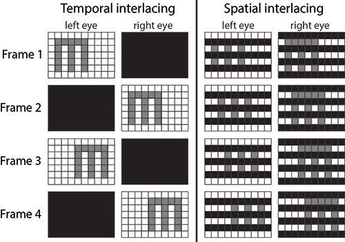
Fig. 1: Temporal interlacing is shown at left and spatial interlacing at right. To illustrate these two protocols, we show the images seen by the left and right eyes with time proceeding from top to bottom. The grid pattern represents individual pixels. The stimulus being displayed is the letter “E” with a height of 5 pixels.
Each method is prone to visible artifacts due to the way the display is sampled in space and time. Temporal interlacing is prone to temporal artifacts, while spatial interlacing is prone to spatial artifacts.
A significant problem with spatial interlacing is lower effective spatial resolution because each eye receives only a half-resolution image at any given time. Some researchers and manufacturers have claimed that the visual system can fuse the two half-resolution images to create a full-resolution image in the visual brain.8,14 But an understanding of how binocular fusion occurs in the human visual system casts doubt on this claim. A fundamental principle in binocular fusion is that image features with dissimilar properties will not be matched in both eyes. Consequently, illuminated pixel rows (or columns) in one eye will almost always be matched with illuminated rows in the other eye and, likewise, non-illuminated rows will be matched in both eyes.12 Because of this, the claim that full-resolution images can be created from two half-resolution images in a spatial-interlacing display is very questionable.
Kim and Banks10 measured effective spatial resolution in spatial- and temporal-interlacing displays. In a series of psychophysical experiments they found that resolution was indeed lower with spatial interlacing, but the resolution loss depended on viewing distance. At short distances, resolution was significantly lower with spatial interlacing than with temporal. At such distances, resolution is display limited, that is, resolution is determined primarily by the density of pixels. Said another way, the pixel rows can be seen at short distance, so fusion occurs with bright rows being matched to bright rows and dark rows to dark rows, thereby creating a fused but half-resolution image. The recommended viewing distances for HDTV and UHDTV fall into this regime.4,5 Kim and Banks found that resolution was equivalent for the two types of interlacing at long viewing distances because, at those distances, resolution is eye limited, that is, resolution is determined primarily by the acuity of the viewer’s eye.
Temporal interlacing is prone to temporal artifacts such as flicker and unsmooth motion appearance.3,7 These artifacts can be best understood by an analysis in the spatio-temporal frequency domain using the concept of the window of visibility.1516 The window represents the range of spatial and temporal frequencies that are visible to a typical viewer. It is depicted by the red diamonds in Fig. 2.
Consider a thin object moving in the world at constant speed. Its spatio-temporal amplitude spectrum (in the Fourier domain) is a diagonal line in plots like that in Fig. 2. When the same object is presented on a digital display, its amplitude spectrum is given by the convolution of the smoothly moving object with the spatio-temporal point-spread function of the display. This creates replicates (or aliases) in the spectrum, which are the diagonals in the figure that do not run through the origin. When the replicates are low in spatio-temporal frequency they fall within the window of visibility and therefore become visible. In this case, the viewer perceives the displayed and real objects as different: the displayed object has visible artifacts such as flicker, judder, and pixelization. Sampling in temporal and spatial interlacing differs, so the spatio-temporal frequencies of the replicates in the two methods differ as well.1,6
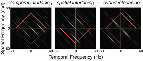
Fig. 2: Shown is the amplitude spectra for temporal- and spatial-interlaced displays. A diagonal line through the center of each plot (from upper left to lower right, not shown in the figure) would be the spectrum for a continuously moving stimulus in the real world. The white diagonal through the center of each plot represents the amplitude spectrum of a stimulus moving at constant speed but presented on a typical display. The other diagonal lines are replicates (aliases) caused by the discrete sampling of the display. The red diamonds represent the window of visibility: spatio-temporal frequencies within the diamond will be visible while frequencies outside the window will not. Temporal and spatial interlacing have different replicate patterns. The differences mean that the two methods produce different visible artifacts. Hybrid interlacing pushes the replicates to higher spatio-temporal frequencies that are less visible to human viewers, and this makes the artifacts less objectionable.
Temporal interlacing creates replicates primarily in temporal frequency, while spatial interlacing creates them primarily in spatial frequency. For this reason, temporal interlacing is prone to artifacts in time such as flicker and judder and spatial interlacing to artifacts in space such as spatial aliasing and pixelization.3,6,10
Hoffman et al.3 and Johnson et al.7 carried out a series of psychophysical experiments to quantify the determinants of the temporal artifacts associated with temporal interlacing. The artifacts include judder (jerky or unsmooth motion appearance), motion blur (apparent smearing in the direction of stimulus motion), and banding (appearance of multiple edges in the direction of stimulus motion).
The researchers observed that the primary determinants of motion artifacts are capture rate (the number of unique images presented per unit time) and the speed of a moving object: artifacts become more visible with decreasing capture rate and increasing speed.3,7 Motion artifacts occurred at higher capture rates and lower stimulus speeds with temporal interlacing than with spatial interlacing because the former requires two sub-frames to present the two images while the latter requires only one. These results were well predicted by the spatiotemporal frequencies created by the two stereoscopic protocols and the degree to which those frequencies fall within the window of visibility.
Another type of artifact occurs with temporal and spatial interlacing: distortions of perceived depth. In temporal interlacing, an object moving horizontally across the screen can appear displaced in depth because of an ambiguity in how the visual system matches left- and right-eye images. With this type of interlacing, the two eyes do not receive images at the same time. Thus, a given frame presented to the left eye could in principle be matched with a preceding or succeeding frame in the right eye.3,13 This is illustrated in Fig. 3.
Depending on how the temporal interlacing is done, one of those matches yields the correct disparity while the other match yields an incorrect disparity. The visual system has no way of knowing which value is correct and which is incorrect, so it averages the two estimates, causing perceived depth to be displaced by an amount that depends on object speed and frame rate. The direction of the depth distortion (object seen as too far or too near) depends on whether the object is moving leftward or rightward. Experimental measurements of perceived depth confirm the predictions of the model depicted in Fig. 3.3,7 One can eliminate this artifact by capturing the image data in stereo cameras in alternating fashion rather than simultaneously.3
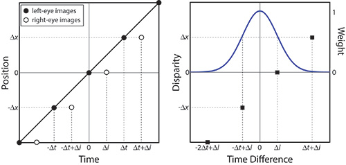
Fig. 3: The charts illustrate disparity computation with temporal interlacing. At left appears a space-time plot of a horizontally moving stimulus on a temporally interlaced display. The stimulus has zero disparity, so it should be seen in the plane of the display screen. Each right-eye image is delayed by Δi relative to each left-eye image. Binocular matches could, in principle, be made between a left-eye image and the succeeding right-eye image or between the left-eye image and the preceding right-eye image. At right is a disparity estimation with weighted averaging over time. The weight given to each potential match is shown by the value on the right ordinate. In this example, the object is seen as closer to the viewer than intended.
Distortions of perceived depth also occur in spatial interlacing. This form of depth distortion is caused by the way the visual system fuses images from both eyes to form a binocular percept. When the pixels are large enough to be resolved (which occurs at short viewing distance), alternating bright and dark pixel rows (or columns) are visible to each eye. The visual system nearly always fuses features with similar luminances (i.e., bright with bright and dark with dark).
To make these matches in a row-by-row temporal-interlacing display, the viewer makes a small vertical vergence eye movement (one eye moves slightly upward while the other moves slightly downward) in order to align bright rows and dark rows in both eyes.2,10 This vertical vergence eye movement causes a change in the horizontal disparity at the retina and therefore a change in perceived depth. The amount of induced horizontal disparity depends on the feature’s orientation: there is no induced disparity for vertical features and successively greater disparity for features that are closer to horizontal. This effect is seen, for example, when viewing an X on the screen. One limb of the X is perceived as closer than it should be and the other limb is seen as farther than intended.2
Alternative Methods
Consideration of the properties of the human visual system has led to two alternative methods for presenting stereoscopic imagery that minimize, and sometimes eliminate, the visible artifacts that plague conventional temporal and spatial interlacing. As we said earlier, temporal interlacing is prone to temporal artifacts such as judder and depth distortion with moving objects, while spatial interlacing is prone to spatial artifacts such as reduced spatial resolution.
Johnson et al.6 proposed a hybrid spatio-temporal-interlacing protocol that is designed to minimize the temporal artifacts associated with temporal interlacing while minimizing the spatial artifacts associated with spatial interlacing. It accomplishes this by sampling differently in space-time in order to move aliases to spatio-temporal frequencies to which the human visual system is insensitive9 (right panel of Fig. 2).
In the hybrid protocol, which is schematized on the left side of Fig. 4, the left- and right-eye views are interlaced spatially, but the rows presented to each eye alternate frame by frame. Johnson and colleagues6 showed that the hybrid protocol retained the benefits of temporal and spatial interlacing while eliminating the shortcomings. Unlike temporal interlacing, it produced no depth distortion with moving objects and had minimal motion artifacts. At the same time, it yielded better spatial resolution than spatial-interlacing displays. The left panel of Fig. 5 shows results from a psychophysical experiment that confirms that depth distortions that occur with temporal interlacing (blue symbols) are eliminated with hybrid interlacing (green).
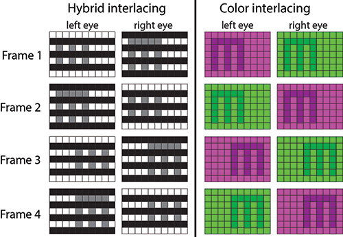
Fig. 4: Hybrid- and color-interlacing methods are illustrated. At left, the hybrid-interlacing protocol presents odd pixel rows to the left eye and even pixel rows to the right eye in one frame, and then even rows to the left eye and odd to the right in the next frame. At right, the color-interlacing protocol presents the green primary (G) to the left eye and the red and blue primaries (R+B) to the right eye at the same time, and then R+B to the left eye and G to the right in the next frame.
Another method, which we call color interlacing, takes advantage of another known property of the human visual system. The visual system converts the signals from the three cone types [long, medium, and short wavelength (L, M, and S)] into a luminance signal (L + M) and two color-opponent signals (L – M or red-green opponent and (L + M) – S or blue-yellow opponent). Disparity is primarily calculated from the luminance signal and not the color-opponent signals. Furthermore, flicker appearance is primarily determined by luminance variation and not color variation.
This color-interlacing method takes advantage of these properties to reduce depth distortion and flicker.11 Each frame is divided into two sub-frames. In the first sub-frame, the image from the green primary is presented to the left eye while the images from the red and blue primaries (i.e., magenta) are presented to the right eye. In the second sub-frame, the colors are reversed so magenta is presented to the left eye and green to the right eye. The presentation is split this way so that both eyes are being stimulated at all times, thereby keeping luminance at the eyes roughly constant over time.
Kim and colleagues11 implemented this protocol and measured depth distortion and flicker. They found that both were significantly reduced with color interlacing compared to conventional temporal interlacing. The depth distortion results are shown on the right side of Fig. 5. Note that depth distortion is eliminated altogether when the displayed color is desaturated (e.g., gray) and that the amount of distortion approaches that in temporal interlacing as the colors become highly saturated. Thus, color interlacing is an attractive approach for reducing artifacts due to temporal interlacing.
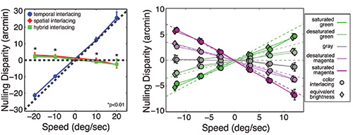
Fig. 5: Two charts illustrate depth distortion in hybrid and color interlacing. At left, hybrid interlacing is compared to temporal and spatial interlacing. The ordinate is the disparity that must be added to a horizontally moving stimulus in order to eliminate depth distortion. The abscissa is the speed of the stimulus. When the added disparity is zero, no depth distortion occurred. At right, color interlacing is compared to temporal interlacing. The ordinate is again the disparity that must be added to a horizontal moving stimulus to eliminate depth distortion. The abscissa is the speed of the stimulus. Different symbols represent the results for different colors.
Better Stereoscopic Displays through Understanding the Human Visual System
Single-screen stereoscopic displays create objectionable artifacts due to the manner in which different images are delivered to each eye. Whether one separates the left- and right-eye images in time or space produces different sorts of problems. We have shown, however, that knowledge of the properties of the human visual
system can be considered in the design of displays that will produce less objectionable artifacts. We hope that these examples will stimulate more ideas in how to dovetail the properties of displays to the visual capabilities of the viewer.
References
1M. S. Banks, D. M. Hoffman, J. Kim, and G. Wetzstein, “3D Displays,” Annual Review of Vision Science 2(1) (2016).
2J. H. Hakala, P. Oittinen, and J. P. Häkkinen, “Depth artifacts caused by spatial interlacing in stereoscopic 3D displays,” Transactions on Applied Perception 12(1), 3 (2015).
3D. M. Hoffman, V. I. Karasev, and M. S. Banks, “Temporal presentation protocols in stereoscopic displays: Flicker visibility,
perceived motion, and perceived depth,” J. Soc. Info. Display 19(3), 271–297 (2011).
4ITU-R Recommendation BT.2022 (2012), General viewing conditions for subjective assessment of quality of SDTV and HDTV television pictures on flat-panel displays, International Telecommunication Union, Geneva, Switzerland.
5ITU-R Recommendation BT.709-5 (2002), Parameter values for the HDTV standards for production and international programme exchange, International Telecommunication Union, Geneva, Switzerland.
6P. V. Johnson, J. Kim, and M. S. Banks, “Stereoscopic 3D display technique using spatiotemporal interlacing has improved spatial and temporal properties,” Optics Express 23(7), 9252–9275 (2015a).
7P. V. Johnson, J. Kim, D. M. Hoffman, A. D. Vargas, and M. S. Banks, “Motion artifacts on 240-Hz OLED stereoscopic 3D displays,” J. Soc. Info. Display 22(8), 393–403 (2015b).
8E. F. Kelley, “Resolving resolution,” Information Display 27(9), 18–21 (2011) .
9D, H, Kelly, “Motion and Vision: II. Stabilized spatio-temporal threshold surface.” J. Opt. Soc. Am. 69, 1340–1349 (1979).
10J. Kim, and M. S. Banks, “Effective Spatial Resolution of Temporally and Spatially Interlaced Stereo 3D Televisions (paper 65.1),” SID Symp. Digest Tech. Papers 43(1), 879–882 (2012).
11J. Kim, P. V. Johnson, and M. S. Banks, “Stereoscopic 3D display with color interlacing improves perceived depth,” Optics Express 22(26), 31924–31934 (2014).
12J. D. Krol and W. A. van de Grind, “Depth from dichoptic edges depends on vergence tuning,” Perception 12, 425–438 (1983).
13J. C. A. Read and B. G. Cumming, “The stroboscopic Pulfrich effect is not evidence for the joint encoding of motion and depth,” J. Vision 5, 417–434 (2005).
14R. M. Soneira, “3D TV display technology shoot out” (2011); http://www.displaymate.com/3D_TV_ShootOut_1.htm
15A. B. Watson, “High frame rates and human vision: A view through the window of visibility,” SMPTE Motion Imaging Journal 122, 18–32 (2013).
16A. B. Watson, A. J. Ahumada, and J. E. Farrell, “Window of visibility: A psychophysical theory of fidelity in time-sampled visual
motion displays,” J. Opt. Soc. Am. 3(3), 300–307 (1986). •
Paul V. Johnson is a display engineer at Apple. He can be reached at pvjohn98@gmail.com. Joohwan Kim is a research scientist with Nvidia. He can be reached at sckim@nvidia.com. Martin S. Banks is a professor of optometry, vision science, psychology, and neuroscience at UC Berkeley. He can be reached at martybanks@berkeley.edu.