Advances in Head-Mounted Light-Field Displays for Virtual and Augmented Reality
Advances in Head-Mounted Light-Field Displays for Virtual and Augmented Reality
Advances in Head-Mounted Light-Field Displays for Virtual and Augmented Reality
Head-mounted light-field displays render a true 3D scene by sampling either the projections of the 3D scene at different depths or the directions of the light rays apparently emitted by the 3D scene and viewed from different eye positions. Head-mounted light-field displays are capable of rendering correct or nearly
correct focus cues and addressing the well-known vergence–accommodation mismatch problems of conventional virtual- and augmented-reality displays.
by Hong Hua
HEAD-MOUNTED DISPLAYS (HMDs) have drawn significant interest in recent years for a broad range of consumer applications.1,2 For instance, a lightweight optical see-through head-mounted display (OST-HMD), which enables optical super-position of two-dimensional (2D) or three-dimensional (3D) digital information onto a user’s direct view of the physical world and maintains see-through vision to the real world, is one of the key enabling technologies for augmented-reality (AR)
applications. HMDs are viewed as a transformative technology, enabling new ways of accessing and perceiving digital information essential to our daily lives. In recent years, significant advancements have been made toward the development of unobtrusive AR displays that integrate the functions of OST-HMDs, smart phones, and various mobile computing functions. A few commercial AR displays have demonstrated very compact and lightweight form factors with the potential of widespread public use. For instance, Google Glass3 is a very compact lightweight monocular display that provides encumbrance-free instant access to digital information, while the Epson Moverio4 and Microsoft Hololens5 are binocular displays providing the benefits of stereoscopic viewing. On the virtual-reality (VR) side, several immersive HMD products are commercially deployed or close to commercial launch.
Despite tremendous progress, minimizing visual discomfort involved in wearing HMDs remains an unsolved challenge. Most existing HMDs utilize 2D flat-image sources located at a fixed distance from the eye, and thus lack the ability to render correct focus cues (including accommodation and retinal image blurring effects) for digital information. The resulting well-known vergence–accommodation conflict (VAC) problem in both VR and AR systems is considered a key contributing factor to visual discomfort. Many studies have investigated the artifacts of the incorrectly rendered focus cues in conventional stereoscopic 3D displays.6–9 Incorrect focus cues may contribute to the two commonly recognized issues: distorted depth perception and visual discomfort, including diplopic vision, visual fatigue, and degradation in oculomotor response.
Several methods have been explored in HMD designs to address the VAC problem and approximate the visual effects created by focus cues when viewing a real-world
scene. Examples include a vari-focal-plane display that dynamically compensates the focal distance of a single-plane display based on a viewer’s fixation point,10,11 a multi-focal-plane (MFP) display method that creates a stack of focal planes in space- or time-multiplexing fashion,12–17 a micro-integral imaging (micro-Inl) method that reconstructs the full-parallax light fields of a 3D scene through pinhole or lenslet array18,19 and a multi-layer method, which utilizes multi-layers of spatial light modulators (SLMs) to modulate a uniform backlight and render apparently directional light rays.20,21 To some extent, these methods are able to overcome the VAC problem with different levels of limitations. In this article, we focus on reviewing recent advancements of head-mounted light-field displays for VR and AR applications, which incorporate some of these methods.
Multi-Focal-Plane Approach toward Head-Mounted Light-Field Displays
A multi-focal-plane (MFP) display creates a stack of discrete focal planes dividing an extended 3D scene volume into multiple zones along the visual axis, each of which only renders 3D objects nearby.12–17 Figure 1 shows a schematic diagram of a dual-focal-plane example. An MFP-based display may be implemented either by spatially multiplexing a stack of 2D displays12,13 or by fast switching the focal distance of a single 2D display sequentially using a high-speed vari-focal element (VFE) in synchronization with the frame rendering of multi-focal images.14–17 For instance, Akeley et al. demonstrated a proof-of-concept bench prototype of a three-focal-plane display covering a fixed depth range from 0.311 to 0.536 m by dividing a flat-panel display into three focal planes through three beamsplitters placed at different distances from the viewer. McQuaide et al. demonstrated a dual-focal-plane retinal scanning display in which a 2D image is generated on a pixel-by-pixel basis by raster scanning a laser beam. The focus of the laser beam is varied through the use of a deformable membrane mirror device (DMMD), and the focus cues can be adjusted at every pixel if the DMMD operates at a high enough speed.14 More recently, Schowengerdt et al. suggested a spatial-multiplexing retinal scanning display by replacing a single fiber source with a fiber array to produce a multi-focal bundle of beams.22 By using a liquid lens as the VFE and an OLED microdisplay as the image source, Liu and Hua demonstrated the first prototype of a dual-focal-plane optical see-through AR display, which maintains a non-obstructive see-through view to
the real world.15 Love et al. demonstrated a prototype with four fixed focal planes generated through birefringent lenses as the VFEs and high-refresh-rate CRTs as the image sources.16 Wu et al. recently demonstrated an MFP prototype by exploring dynamically variable planes adapted from contents.23
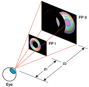
Fig. 1: This schematic shows the multi-focal-plane display method.
In these conventional MFP display methods, a large number of focal planes and small dioptric spacing are desirable for achieving accurate focus cues. It was suggested that the dioptric spacing between adjacent focal planes should be 1/7 diopters to achieve 1 arc-minute spatial resolution.12 At this spacing, 28 focal planes are needed to cover the depth range from infinity to 4 diopters. A depth-fused 3D (DFD) multi-focal plane (DFD-MFP) display method was proposed (Fig. 2), through which the number of necessary focal planes is effectively reduced to an affordable level.17,24–29 Liu and Hua,17 Hu and Hua,25 and Hu26 presented a framework for a DFD-MFP system design in which the focal-plane spacing and the fusion functions are optimized to maximize the contrast magnitude and gradient of the retinal image fused by the two images overlapping along the visual axis. This framework avoids a conflict of focusing cues and creates a smooth contrast
gradient that helps to stimulate and stabilize the eye accommodation response.
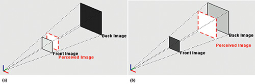
Fig. 2: In this schematic model of a DFD-MFP display, the luminance ratio between the front and back images is modulated to change the
perceived depth of the fused image to be near to the front image plane (a) and near the back image (b).
Figure 3 shows the optical layout of a monocular OST-HMD system based on the DFD-MFP
method.27 Each monocular setup consists of two parts: the composite optical see-though eyepiece and the image-generation subsystem (IGS). The composite eyepiece [Fig. 3(a)] consists of a wedge-shaped freeform eyepiece, a free-form see-through compensator lens, and a cylindrical lens.27 The IGS [Fig. 3(b)] achieves the core function of generating the multi-focal-plane contents. It consists of a 0.7-in. high-speed digital-mirror-device (DMD) microdisplay, a deformable membrane mirror device (DMMD), and relay lens groups. The DMD display, illuminated by an RGB LED light source (not shown), is first magnified by two field lenses and then relayed by a double-pass double-telecentric lens group, forming an intermediate image between the IGS and the eyepiece. By changing the optical power of the DMMD, the intermediate image shifts axially with respect to the eyepiece without magnification change, while the accommodation cue of the HMD is varied from far to close. The optical power of the DMMD can change at a speed as fast as 1 kHz; thus, virtual images at multiple focal distances can be multiplexed by rapidly changing the optical power of Mthe DMD.
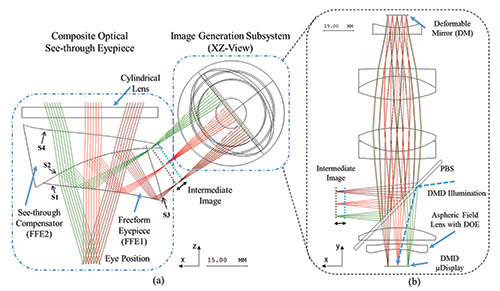
Fig. 3: (a) A top-view optical layout of the right-eye module of a DFD-MFP system includes (b) a detailed layout of the image-generation subsystem.27
Figure 4(a) shows the actual setup built on an optical bench.27 Figures 4(b) and 4(c) show photos of a 3D scene rendered by the virtual display and captured with a camera placed at the exit pupil position.27 Six focal planes were dynamically formed at 3.0, 2.4, 1.8, 1.2, 0.6, and 0.0 diopters, respectively, at an overall refresh rate of 60 Hz. The 3D scene consists of a green floor grid extending from 3.0 to 0.6 diopters, a green wall grid at 0.6 diopters having a University of Arizona logo on it, and a grating target extending from 3.0 to 0.6 diopters, as well as a College
of Optical Sciences logo placed at the 3.0 diopter end. Each focal plane displays a different part of the 3D scene. By incorporating non-linear depth-fusing functions,25 this 3D scene was rendered continuously by five of the focal planes. Figure 4(b) shows the image with the camera focusing at a 3-diopter distance (near), andFig. 4(c) shows the image focusing at a 0.6-diopter distance (far). Natural focus cues were clearly demonstrated, and high-contrast targets were correctly fused across focal planes, which visually validated the depth-fusion display method. The optical see-through path of the prototype also achieved superb performance.
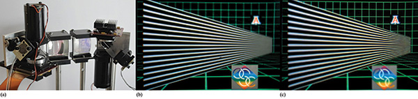
Fig. 4: A multi-focal-plane prototype system with freeform eyepiece (a) is shown with an example of 3D images rendered by the prototype for a camera at near focus (b) and at far focus (c).27
Overall, the prototype adequately demonstrated the capability of the DFD-MFP display method for rendering nearly correct focus cues, with the potential for addressing the VAC. However, the technology suffers from several critical technical obstacles to becoming a viable solution for truly wearable light-field AR displays. The first major obstacle is miniaturization of the technology. Due to the limitations of several enabling technologies, including the high-speed displays and vari-focal element, the current prototype was implemented in the form of a bench prototype, occupying a volume of nearly 500 × 300 × 100 mm. The second major obstacle is real-time rendering and display. The prototype is limited by the current capabilities of high-speed display technology and display–computer interfaces and is unable to render and display six or more frames of high-resolution full-color images at a speed several times faster than a standard single-frame display. Transforming this display method into a compact wearable solution requires several technical innovations.
Integral-Imaging (InI) Based Head-Mounted Light-Field Displays
Instead of creating a stack of focal planes to sample the depth volume, an integral-imaging (InI) based display method reconstructs the full-parallax light fields of a 3D scene by densely sampling the different directions of the light rays apparently emitted by a 3D scene.30 A simple InI display typically consists of a display panel and a microlens array (MLA). The display renders a set of 2D elemental images, each of which represents a different perspective of a 3D scene. The MLA creates the perception of a 3D scene that appears to emit light and
occupy 3D space, through the intersection of the ray bundles emitted by the corresponding pixels in the elemental images. The InI-based display allows the reconstruction of a 3D shape with full-parallax information in both horizontal and vertical directions. The simple optical architecture of InI makes it attractive to integrate with an HMD optical system to create a wearable true 3D display.
Lanman et al. demonstrated a non-see-through light-field display by directly placing an MLA and an OLED microdisplay in front of the eyes to render the light field of a 3D scene for VR applications.19 The prototype system, shown in Fig. 5, had a field of view of about 29° × 16° and a spatial resolution of 146 × 78 pixels. Hong et al. demonstrated a prototype of an integral floating display system using a convex half-mirror as the eyepiece.31 The prototype system, however, had only a few degrees of FOV and did not demonstrate a useful see-through capability in a wearable device.
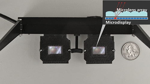
Fig. 5: This non-see-through head-mounted near-to-eye light-field-display prototype was demonstrated by Lanman in 2013.19
Hua and Javidi demonstrated the first practical implementation of an OST-HMD design that integrated a microscopic InI (micro-InI) method for full-parallax
3D scene visualization with free-form optical technology for OST-HMD eyepiece optics.18 This approach enabled a compact 3D OST-HMD (InI-OST-HMD) with full-parallax light-field rendering capability. Figure 6(a) shows the schematic optical layout. The optics consist of a micro-InI unit, a wedge-shaped freeform eyepiece,32 and a see-through freeform corrector lens. The micro-InI unit, consisting of a high-resolution microdisplay and an MLA, reproduces the full-parallax light fields of a 3D scene. which replaces a conventional 2D microdisplay as the image source. The freeform eyepiece optics directly relays the reconstructed 3D light fields into a viewer’s eye for viewing, and the see-through lens cemented with the free-form prism optically enables nonobtrusive viewing of the real-world scene.
A prototype was demonstrated by utilizing a 0.8-in. OLED, an MLA with a 3.3-mm focal length and 0.985-mm pitch, a wedge-shaped freeform eyepiece with an equivalent focal length of 28 mm, and a see-through compensator. The gap between the microdisplay and MLA was about 4.3 mm, and the reference plane of the micro-InI unit was approximately 10 mm away from the MLA. After being magnified by the eyepiece, the virtual reference plane of the reconstructed 3D scene in the visual space was approximately 1 diopter away from the exit pupil of the eyepiece. An array of 12 × 11 elemental images was simulated, each of which consists of 102 × 102 color pixels. The FOV of the reconstructed 3D scene by the eyepiece was about 33.4° diagonally. The spatial resolution of the reconstructed 3D scene by the micro-InI unit was about 22.4 μm on the reference plane, which yielded an angular resolution of 2.7 arc-minutes on the virtual reference plane in the visual space.
Figure 6(b) and 6(c) show two views captured by a digital camera focusing at 0.25 diopters and 3 diopters, respectively. In the see-through view, two physical references, a Snellen eye chart and a resolution grating, were placed at a distance of 0.25 and 3 diopters, respectively, from the camera. In the virtual view, three columns of the letter “E” were rendered at a distance of 0.25, 1, and 3 diopters, respectively. The letters on the bottom, which were half the size of the letters on the top row, were about the same size as the largest letter on the Snellen chart, with a similar stroke width or gap. The gap or stroke of the largest letter on the Snellen chart represented an angular resolution of 15 minutes of arc at the distance of 4 m.
The results clearly demonstrate that an InI-based HMD method can produce correct focus cues and true 3D viewing in a large depth range. On the other hand, artifacts are visible in these images. Just like the InI-based autostereoscopic method for eyewear-free displays, the InI-HMD method is subject to the limitations of low lateral and longitudinal resolutions, shallow depth of field, narrow viewing angle, crosstalk due to the limited imaging capability and finite aperture of the MLAs, poor spatial resolution of the displays, and a trade-off relationship between wide viewing angle and high lateral and longitudinal resolutions. Further technological innovations are needed to improve the optical performance.
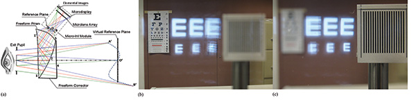
Fig. 6: An optical see-through head-mounted near-to-eye light-field-display prototype uses free-form optical technology. Shown from left to right are a schematic layout (a) and a photograph captured with a camera focusing at 0.25 diopters (b) and at 3 diopters (c).18
Computational Multi-Layer Light-Field Displays
Unlike the additive multi-focal-plane approach to light-field rendering, Wetzstein et al. described a multiplicative light-field-display technique utilizing a stack of time-multiplexed light-attenuating layers illuminated by either a uniform or directional backlight for autostereoscopic displays.21 The modulation pattern of each layer was optimized to produce images for a desired viewing zone. Maimone et al. demonstrated the feasibility of stimulating correct eye accommodation by synthesizing dense samples of the light fields over the eye pupil.33
Maimone and Fuchs applied the multilayer computational light-field-display technique to HMDs and demonstrated a computational multilayer AR display.20 A stack of transparent SLMs, a thin transparent backlight, and a high-speed shutter were sandwiched with a small spacing between the SLM layers. Figure 7(a) shows a schematic layout and Fig. 7(b) shows a prototype implementation. The sandwiched stack is placed directly in front of the eye, without any other focusing optics placed in between the display stack and the eye. The device operates in two modes: augmented image-rendering mode (shutter off) and the occluded real-world image-formation mode (shutter on). In the augmented view mode, the real-world view is blocked and a set of optimized patterns are rendered on the SLM layers to attenuate the light rays from the backlight and produce the final color of the rays entering the eye, which is the product of the attenuation values assigned to each of the intersected pixels across the layers. By reproducing a set of rays with adequate angular resolution over the eye pupil that appear to be emitted from a virtual object at an apparent location far from the device stack, the display is able to reconstruct the light field of a 3D virtual object and potentially provide correct focus cues. In the real-world image-formation mode, the backlight is turned off and the shutter is turned off. Occlusion masks can be displayed on the SLM layers to allow selective transmission of the real-world rays, enabling mutual occlusion between virtual and real-world scenes.
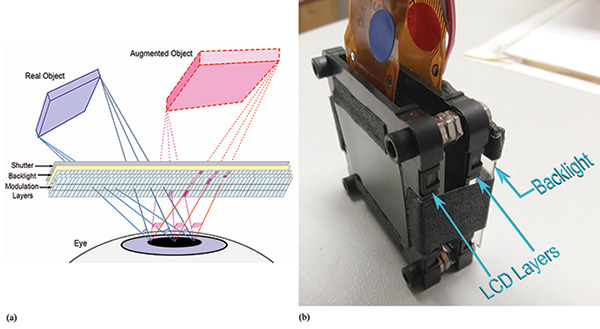
Fig. 7: A computational multi-layer optical see-through light-field display: (a) a schematic layout and (b) prototype implementation.20
Due to the close proximity of the SLM stack to the eye, this method could potentially achieve a compact OST-HMD with a wide FOV. Because of the light field’s rendering nature, it can also potentially render correct focus cues and mutual occlusion capabilities. The researchers’ early prototype demonstrated these capabilities to some extent. On the other hand, the limitations of this approach are also obvious and require significant innovations to enable improvements. For instance, both the rendered augmented views, although recognizable, suffer dramatic resolution loss due to diffraction effects through the SLM stack. The see-through view of the real world is blurry and low in contrast due to the diffraction effects of the SLMs as well as the partial transparency of the backlight. The technique is computationally intensive, which requires significant effort to reduce the optimization time to enable real-time use for AR displays. Finally, the prototype also suffers from high light loss due to the low transmittance of the SLM stack.
More recently, Wetzstein et al. extended their multi-layer factored light-field autostereoscopic display method and demonstrated a light-field stereoscope for immersive VR applications.34 The schematic layout and the prototype implementation are shown in Figs. 8(a) and 8(b), respectively. The prototype consists of two stacked LCD panels with a gap of 53 cm in between and a pair of simple magnifier lenses with a focal length of 5 cm for each eye. Modulation patterns are computed using a rank-1 light-field factorization process to synthesize and render the light field of a 3D scene. Although their preliminary demonstration is promising, this approach is subject to a diffraction limit due to the fact that the virtual image pattern on the rear display panel is observed through the front panel.
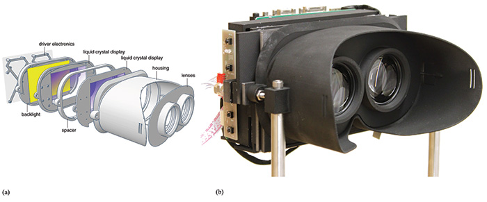
Fig. 8: A computational multi-layer light-field stereoscope appears in (a) the schematic layout and (b) prototype implementation.34
Commercial Light-Field HMDs Are Still in the Future
Clearly, as outlined in this article, recent progress has been made in the development of head-mounted light-field displays for augmented- and virtual-reality applications. Despite the tremendous progress in past decades, all of the existing technical approaches are subject to different tradeoffs and limitations. The MFP display method is capable of rendering correct focus cues for a 3D scene across a large depth volume at high spatial resolution comparable to conventional non-light-field HMD methods, but it has to overcome several critical obstacles to become a compact wearable-display solution. The micro-InI-based light-field-display approach is able to render correct focus cues for a large depth volume, but its optical performances, including spatial resolution, depth of field, longitudinal resolution, and angular resolution, are relatively low compared to the MFP approach. The computational multi-layer approach is still in its preliminary development stage and requires significant innovations to overcome some fundamental limitations such as diffraction artifacts.
We still have a long way to go to engineer head-mounted displays with compact and portable form factors and high optical performance. However, based on the recent pace of development, I am confident that substantial progress and breakthroughs will be made over the next 5 years, making possible the commercial launch of head-mounted light-field displays for consumer applications.
Acknowledgments
Part of the work reviewed is funded by National Science Foundation Grant Awards 0915035 and 1422653. Materials in this review article are partially based on co-authored papers and the Ph.D. dissertation work on the development of multi-focal-plane displays by Dr. Sheng Liu and Dr. Xinda Hu who were former graduate students affiliated with the 3D Visualization and Imaging Systems Laboratory at the University of Arizona. I would also like to acknowledge the collaborative work on the
integral-imaging-based display method with Prof. Bahram Javidi at the University of Connecticut and thank Dr. Doug Lanman, Dr. David Luebke, Prof. Henry Fuchs, and Prof. Gordon Wetzstein for giving me the permission to use the figures in their publications. Finally, I would like to acknowledge Dr. Nikhil Balram for his generous help in editing the article.
References
1R. Azuma, Y. Baillot, R. Behringer, S. Feiner, S. Julier, and B. Macintyre, “Recent advances in augmented reality,” IEEE Computer Graphics and Applications 21(6), 34–47 (2001).
2S. Feiner, “Augmented reality: A new way of seeing,” Scientific American 54 (2002).
3http://www.google.com/glass/start/
4http://www.epson.com/cgi-bin/Store/jsp/Moverio/Home.do
5http://www.microsoft.com/microsoft-hololens/en-us
6J. P. Wann, S. Rushton, and M. Mon-Williams, “Natural Problems for Stereoscopic Depth Perception in Virtual Environments,”Vision Research 35(19), 2731–2736, (1995).
7T. Inoue and H. Ohzu, “Accommodative Responses to Stereoscopic Three-Dimensional Display,” Applied Optics 36(19), 4509–4515 (1997).
8D. M. Hoffman, A. R. Girshick, K. Akeley, and M. S. Banks, “Vergence-Accommodation Conflicts Hinder Visual Performance and Cause Visual Fatigue,” J. Vision 8(3), 1-30 (2008).
9S. J. Watt, K. Akeley, M. O. Ernst, and M. S. Banks, “Focus Cues Affect Perceived Depth,” J. Vision 5(10), 834–862 (2005).
10S. Shiwa, K. Omura, and F. Kishino, “Proposal for a 3-D display with accommodative compensation: 3DDAC,” J. Soc. Info. Display 4(4), 255–261, (1996).
11S. Liu, H. Hua, and D. Cheng, “A novel prototype for an optical see-through head-mounted display with addressable focus cues,” IEEE Trans. Vis. Comput. Graph. 16, 381–393 (2010).
12J. P. Rolland, M. Kureger, and A. Goon, “Multifocal planes head-mounted displays,” Applied Optics 39(19), 3209–3214 (2000).
13K. Akeley, S. J. Watt, A. R. Girshick, and M. S. Banks, “A Stereo Display Prototype with Multiple Focal Distances,” ACM Trans. Graph. 23, 804–813 (2004).
14S. C. McQuaide, E. J. Seibel, J. P. Kelly, B. T. Schowengerdt, and T. A. Furness, “A retinal scanning display system that produces multiple focal planes with a deformable membrane mirror,” Displays 24(2), 65–72, (2003).
15S. Liu and H. Hua, “Time-multiplexed dual-focal-plane head-mounted display with a fast liquid lens,” Optics Letter34(11), 1642–4164 (2009).
16G. D. Love, D. M. Hoffman, P. J. W. Hands, J. Gao, A. K. Kirby, and M. S. Banks, “High-speed switchable lens enables the development of a volumetric stereoscopic display,” Opt. Express 17(18), 15716–15725 (2009).
17S. Liu and H. Hua, “A systematic method for designing depth-fused multi-focal plane three-dimensional displays,” Opt. Express 18(11), 11562–11573 (2010).
18H. Hua and B. Javidi, “A 3D integral imaging optical see-through head-mounted display,“ Optics Express 22(11), 13484–13491 (2014).
19D. Lanman and D. Luebke, “Near-eye light field displays, “ Proc. ACM SIGGRAPH (ACM Transaction on Graphics) (2013).
20A. Malmone, and H. Fuchs, “Computational augmented reality eyeglasses,” Proc. ISMAR, 29–38, (2013).
21G. Wetzstein, D. Lanman, M. Hirsch, and R. Raskar, “Tensor Displays: Compressive light field synthesis using multilayer displays
with directional backlighting,” Proc. ACM SIGGRAPH (ACM Transaction on Graphics) (2012).
22B. T. Schowengerdt, M. Murari, and E. J. Seibel, “Volumetric display using scanned fiber array,” SID Symp. Digest of Tech. Papers (2010).
23W. Wu, I. Tosic, N. Bedard, P. Llull, K. Berkner, and N. Balram, “Near-eye display of light fields, presented at IDW 2015.
24S. Suyama, S. Ohtsuka, H. Takada, K. Uehira, and S. Sakai, “Apparent 3-D image perceived from luminance-modulated two 2-D images displayed at different depths,” Vision Res. 44(8), 785–793 (2004).
25X. Hu and H. Hua, “Design and Assessment of a Depth-Fused Multi-Focal-Plane Display Prototype,” Disp. Technol. J. 1 (2014).
26X. Hu, Development of the Depth-Fused Multi-Focal-Plane Display Technology, Ph.D. Dissertation, College of Optical Sciences, University of Arizona (2014).
27X. Hu and H. Hua, “High-resolution optical see-through multi-focal-plane head-mounted display using
freeform optics,” Optics Express 22(11), 13896–13903 (2014).
28X. Hu and H. Hua, “Distinguished Student Paper: A Depth-Fused Multi-Focal-Plane Display Prototype Enabling Focus Cues in Stereoscopic Displays,” SID Symposium Digest of Technical Papers 42, paper 48.1, 691–694 (2011).
29S. Ravikumar, K. Akeley, and M. S. Banks, “Creating effective focus cues in multi-plane 3D displays,” Opt. Express 19, 20940–20952 (2011).
30G. M. Lippmann, “Epreuves Reversibles Donnant la Sensation du Relief,” J. Phys. 7, 4th series, 821–825 (1908).
31J. Hong, S. Min, and B. Lee, “Integral floating display systems for augmented reality,” Applied Optics 51(18), 4201–4209 (2012).
32D. Cheng, Y. Wang, H. Hua, and M. M. Talha, “Design of an optical see-through head-mounted display with a low f-number and
large field of view using a freeform prism,” Appl. Opt. 48, 2655–2668 (2009).
33A. Maimone, G. Wetzstein, M. Hirsch, D. Lanman, R. Raskar, and H. Fuchs, “Focus 3D: compressive accommodation display,” ACM Trans. Graphics 32(5), 153:1–153:3 (2013).
34F. Huang, K. Chen, and G. Wetzstein. “The Light Field Stereoscope: Immersive Computer Graphics via Factored Near-Eye Light Field Displays with Focus Cues,” ACM SIGGRAPH (Transactions on Graphics), 33(5) (2015). •
Hong Hua is with the 3DVIS Lab, College of Optical Sciences, University of Arizona. She can be reached at hhua@optics.arizona.edu.