Light-Field Displays and Extreme Multiview Rendering
Light-Field Displays and Extreme Multiview Rendering
Light-Field Displays and Extreme Multiview Rendering
Light-field displays have moved beyond the realm of science fiction, with prototypes now existing in the real world. Light-field computation, however, is the barrier to deployment. The sheer number of pixels required to produce high-fidelity light-field content at a reasonable cost represents a daunting though not unsolvable problem.
by Thomas Burnett
If science fiction movies are any predictor of the future, then light-field
displays are inevitable. In past years, rockets, moon landings, and self-driving cars were foretold in popular sci-fi media. In fact, it is hard to recall a recent sci-fi movie without a light-field visualization system at the center of a battlespace planning session or medical procedure visualization. And if battle-space and medical visualization become reality, then viewing of sports and other forms of entertainment in the home is also inevitable, since these visualization challenges are a subset of the aforementioned applications.
A light-field display produces 3D aerial imagery without head tracking and/or eyewear by reproducing the light that would reflect off an object if it were physically present in front of the viewers. A light-field display computes the synthetic light rays from a 3D model/scene in the form of pixels, which are subsequently converted to photons by a very high-density spatial light modulator (SLM). The projected photons/rays are then angularly distributed by a lensing system without regard to the number of viewers, viewer position, or viewer gaze direction.
There have been research studies highlighting the cognitive benefits of 3D light-field visualization. In 2013, Dr. Matthew Hackett at Army Research Labs in Orlando, FL, produced a study comparing medical anatomy training using traditional 2D photos vs. using 3D light-field holograms, and concluded there was a significant decrease in the cognitive load on the student and an increase in memory retention with the 3D holograms.1 Similarly, a 2009 study investigating geospatial light-field holograms on SWAT team routing planning and wayfinding performance concluded that 3D holographic topographic maps increased mission performance within complex 3D operational environments.2
These kinds of studies highlight the key benefits of perspective-correct, full-parallax, 3D aerial light-field projections. With a projected 3D scene including the essential depth cues expected by the human visual system, such as occlusion, specular highlights, and gradient shading, a viewer can decompose a complex 3D scene into a more memorable experience or more actionable intelligence. By presenting a 3D aerial scene in a manner expected by the viewer, the cognitive load on the viewer is decreased, allowing him to make better decisions with greater confidence. In addition, since light-field displays project 3D aerial imagery without head-mounted glasses to interfere with natural communication, the level of collaboration among viewers increases (Fig. 1). This is why light-field displays are inevitable.
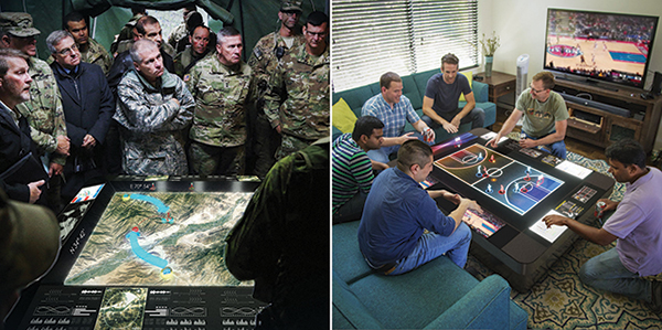
Fig. 1: Light-field display use cases include battle-space planning (left) and gaming/sports visualization (right).
Light-Field Display Architecture
The light-field display architecture shown in Fig. 2 consists of four major subsystems:3
• Hogel optics refers to the array of micro-optics responsible for angularly distributing the light-field rays. The light-field display projection frustum is the union of all the micro-frustums of all the micro-lenses. From any position in the light field, a viewer sees a single ray projected from each microlens. The term “hogel,” which stands for holographic element, is used to describe the 2D set of ray data projected through each microlens.
• The photonics subsystem is an array of SLMs whose function is to convert pixelized ray data (the hogel) into actual light rays. Pixel density at the combined SLM image plane is essential to projecting high-fidelity 3D aerial imagery, assuming the pixel-ray data can be preserved when angularly distributed by the hogel optics.
• The drive electronics subsystem manages the pixel hogel data delivery and synchronization across SLMs. In addition, the drive electronics perform spatial distortion and color corrections on a per-hogel basis.
• Radiance image computation is the subsystem responsible for rendering or computing the light-field rays from a 3D model/scene. The update rate of the light-field display is a function of the input model complexity (number of polygons, textures, materials, and their representation, etc.), the number of compute elements in the cluster, and the number of hogel views rendered to complete the radiance image.
The radiance image computation subsystem receives a 3D model from a host application. This differs from traditional display systems in which the host application dictates draw commands to a closely bound graphics processing unit (GPU) that in turn renders a video stream to the display. By passing the scene to the radiance image computation system, rendering the 3D aerial image becomes the responsibility of the light-field display.
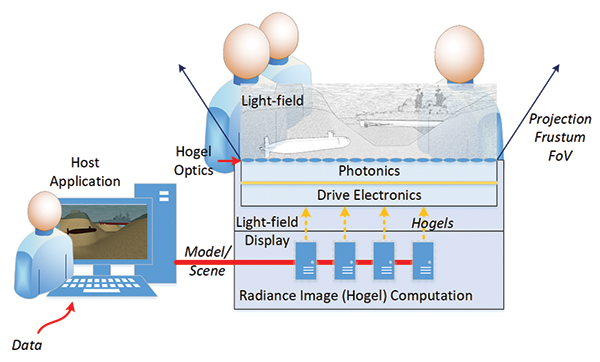
Fig. 2: This light-field display architecture schematic highlights the four major subsystems of the display system: hogel optics, photonics, drive electronics, and radiance image computation.
Light-Field Rendering: In the context of the light-field display, light-field rendering is the process by which the synthetic light-field radiance image is rendered. The light-field radiance image is a raster description of a light field where pixels represent the origin, direction, and intensity of light rays within the light field as described by the plenoptic function in equation (1):4
L = P(Θ, φ, λ, Vx, Vy, Vz) (1)
Whereas a light-field camera captures the light-field radiance image by segmenting incoming light through a microlens array, thus preserving spatial and angular details of rays in the form of pixels, the light-field display computes a synthetic radiance image from a 3D scene/model and projects the radiance image through a microlens array to construct a 3D aerial image.4 Binocular disparity, occlusion, specular highlights, gradient shading, and other expected depth cues within the 3D aerial image are correct from the viewer’s perspective as in the natural, real-world light field.
The light-field display radiance image consists of a 2D array of hogels, each of which represents the direction and intensity of light rays passing through the hogel center (Fig. 3). Consequently, a hogel is a radiance micro-image for a single microlens depicting the scene as projected onto the top plane of the microlens frustum.
The light-field display radiance image is similar to the radiance image as captured by a plenoptic camera; however, the hogel can represent light rays originating from either side of the light-field display hogel plane. This capability effectively doubles the projection depth potential of a light-field display. The light-field display radiance image is synthetically constructed by rendering hogel views from the perspectives of an array of microlenses defined in world space. As such, it requires not only a 3D model of a scene as input, but also a 3D model of the microlens array transformed into the world space of the radiance image rendering engine. Since the radiance image is composed of a microimage for each microlens, many hogel views are rendered to create one radiance image per update of the light-field display.
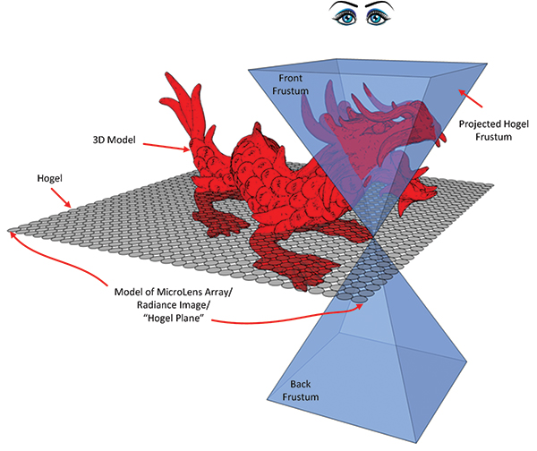
Fig. 3: Above is a double-frustum hogel projection of a single hogel. The radiance image is a 2D array of these hogels.
Light-Field 3D Aerial Fidelity: The radiance image is converted into light/photons by an array of SLMs, which project the light rays through an array of microlenses (hogel optics). The microlenses angularly distribute the radiance image light rays to construct a full-parallax 3D aerial image. As the pixels project through a microlens array, the resulting projected 3D image exhibits the classic light-field spatial/angular trade. In essence, the size, arrangement, and number of microlenses within the array
defines the spatial resolution at the image plane of the light-field display. The number of pixels behind each microlens (the hogel size) determines
the potential depth projection and resolution characteristics at height within the 3D aerial image.
The term directional resolution (Dr) is often used to describe the number of views that a hogel microlens can project along one axis. The total number of rays that are projected through a hogel is Dr × Dr. Angular pitch (Ap)a is a measure of the angular beam spread/divergence and is determined from the directional resolution and microlens field of view (FoV) by equation (2):
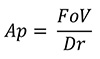 (2)
(2)
Increasing the pixel density behind each hogel can potentially increase 3D aerial image fidelity and achievable depth if the detail can be preserved when angularly distributed by the microlens array. Therefore, having small angular pitch is desirable and Ap can be used to describe a display’s ability to project detail at height above the display plane. However, 3D spatial resolution, projection accuracy, color fidelity, and brightness degrade as the projection distance from the image plane increases.
Light-Field Rendering Algorithms
There are a few processes for generating hogel data (rendering the radiance image); the difference between the two most common rasterization approaches is the order in which they decompose the 4D light field (two dimensions of position, two dimensions of direction) into 2D rendering passes. The most direct rasterization method is by use of the double-frustum hogel-rendering algorithm, which processes all directions for a single hogel simultaneously.5 A second algorithm, known as oblique slice and dice, processes all the rays for a single direction simultaneously and is better suited for small-area displays that can afford a huge pixel transform.
Double-Frustum Hogel Rendering: Double-frustum rasterization of the radiance image entails placing the virtual camera at the hogel center in world space and rendering the scene downward from the display plane; the camera is then flipped and rendered upward without clearing the depth buffer. The front camera is rendered preserving triangles farthest from the
camera, thus closer to the viewer. When the two views are combined via their depth buffers, the hogel “bowtie” frustum is created (Fig. 3). The “bowtie” frustum represents the direction and intensity of light passing through the hogel center; thus, the rendered viewport is the hogel. This process is repeated for every hogel for every update of the scene.
The double-frustum algorithm has the advantage of rendering a hogel natively, in that the hogel can be subsequently projected with no further processing. However, the double-frustum algorithm does require two passes of the geometry to create the double frustum and there can be a mathematical singularity at the center of the bowtie.
At least within the fixed-function OpenGL render pipeline, the camera matrix cannot have a non-zero near plane. Any geometry that passes between the near planes of the front and back frustums is clipped. One way to resolve this issue is to offset the front and back frustums so that the near planes overlap. This negates the singularity in most cases, but is not a perfect solution in that the center of the bowtie becomes a small plane that can still exhibit mathematical anomalies that result in corrupted hogels.
Oblique Slice and Dice Hogel Rendering: The oblique slice and dice algorithm uses an orthographic camera projection with a shear applied to render all the pixels for a particular view direction during each pass of the geometry. The shear matrix is adjusted for each projection direction the light-field display can produce (Fig. 4). A display that has a 90° FoV with 256 × 256 pixels (rays) per hogel would require 2562 render passes with a -45° to 45° shear applied in 2 dimensions in (90/256) increments.
Oblique rendering typically makes better use of the GPU in that the algorithm renders to larger framebuffers within GPU memory, and in some cases, requires fewer passes of the geometry than the double-frustum algorithm. However, the rendered pixels are not in a spatial form that can be projected through a microlens array and must undergo a pixel transform from
oblique render space to hogel space (Fig. 4).
The pixel transform requires either a buffer that stores the entire rendered oblique data in advance of the pixel transform, which needs its own destination buffer of equal size; or a pixel transform engine that requests views that are rendered on demand and partially transformed depending on the available memory to store complete hogels. In the latter case, views are often re-rendered many times so that all the available memory is preserved for assembling as many hogels as possible per light-field display update. If the memory is not all co-located within a single computer and is spread across multiple machines, then the pixels must be pushed across an interconnect framework, which greatly increases the time to perform the pixel transform. As such, oblique slice and dice is not as usable in real-time solutions as double-frustum rasterization for large-area light-field displays.
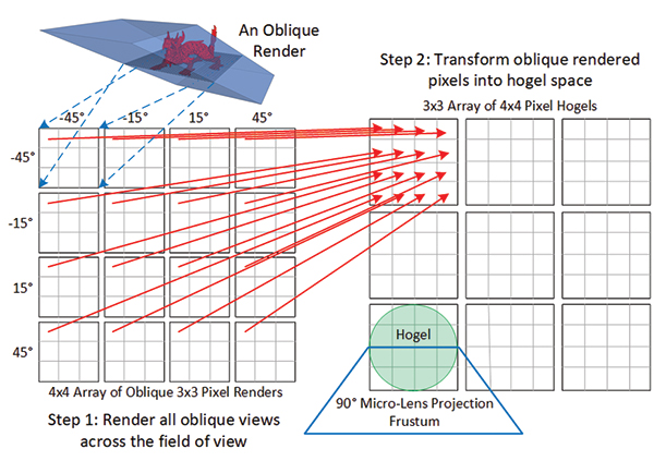
Fig. 4: Oblique view projection incorporates pixel transform. Step 1 is rendering all the views; Step 2 transforms the pixels into a format for projection through a microlens array.
Light-Field Radiance Image-Render Acceleration
There are several high-level processes by which the light-field display radiance image rendering can be accelerated. However, these optimizations are controlled by the centralprocessing unit (CPU) side of multiview rendering and require implementation and management within the host application and/or render engine. In addition, their effect on the radiance image-render rate is different depending on the hogel-rendering algorithm.
Bounding Volumes: Bounding volumes are a standard mechanism used to accelerate rendering. Bounding volumes of geometric entities within the scene are checked for intersection with the virtual rendering camera; only geometries whose bounding volumes intersect the camera frustum are rendered. The double-frustum algorithm benefits significantly since the clipping frustum is tightly bound to a hogel’s projection frustum, and only hogels whose frustums intersect the bounding volume of changed geometry need to be rendered. The oblique-view-clip frustum contains all the rays from each hogel in a particular direction; thus, oblique clip frustum is highly likely to intersect changed geometry whether or not an individual hogel frustum actually intersects that geometry. Therefore, bounding volumes have less impact (or no impact) on the oblique rendering rates.
Table 1 highlights an example of the effect of bounding volume rendering on a mountainous terrain model consisting of 1,340,190 triangles. The terrain mesh was batched into triangle strips with bounding volumes to enable intersection tests. The radiance image rendered consisted of 500 × 500 hogels, each having 256 × 256 pixels for a total of 16,384,000,000 pixels. When rasterizing the whole-terrain radiance image, the double-frustum algorithm benefited greatly from small batch size; the oblique algorithm render rates did not vary significantly with the batch size. Again, it bears mention that the oblique data would still need to undergo the pixel transform into hogel space before display.
Table 1: Below are render times for 500 × 500 hogel (256 × 256 pixels) radiance imagery.
| Algorithm |
~Batch Size (Triangles) |
# Bounding Volumes |
Hogels per second |
Render Time (seconds) |
| Double Frustrum |
3,000 |
441 |
3,691 |
68 |
| Double Frustum |
20,000 |
64 |
1,839 |
136 |
| Double Frustum |
83,000 |
16 |
842 |
297 |
| Double Frustum |
1,330,745 |
1 |
432 |
579 |
| |
|
|
Frames per second |
|
| Oblique: W/O Transform |
3,000 |
441 |
689 |
95 |
| Oblique: W/O Transform |
20,000 |
64 |
829 |
79 |
| Oblique: W/O Transform |
83,000 |
16 |
842 |
78 |
| Oblique: W/O Transform |
1,330,745 |
1 |
848 |
77 |
Foreground/Background Segmentation: Since the collaborative light-field display is typically used to offer a top-down view into a scene, there are usually two modes in which the view-volume transform is used. Either the view-volume transform is related to a particular object transform by which the light-field projection follows an object, or the view-volume transform is independent of any object and in many cases rarely updated.
Consider that if the light-field display were used to project a football game, one mode of operation would be when the display-view volume is fixed to encompass the entire field and the other visualization mode follows a player. If the field, player, and ball geometry were separately defined as foreground and background objects, then triangles would only need to be rasterized when transformed. If the view-volume transform was set once, then the background geometry would only need to be rendered once. The geometry in motion (players and ball) would be rendered every cycle. This technique requires appropriate layer fusion capabilities within the display; however, the segmentation of geometry is defined within the host application.
Multiview (Hogel) Rendering
3D displays require the generation of more than one view per update of the display. At a minimum, stereo projection requires two views. Lenticular, multidepth plane, and volumetric displays are examples of multiview displays, while collaborative light-field displays that project radiance images could be classified as extreme multiview displays. With regard to display projection systems, there are two viewing perspectives to be considered for multiview 3D displays: first-person perspective and display-centric perspective.
First-Person Perspective: The first-person perspective renders the scene relative to a single viewer. The first-person view is the normal view users expect when viewing any 2D video source or 2D/3D game on a standard 2D monitor. In reality, any scene projected/rendered from a single reference point and orientation is in effect first-person. This includes stereo-rendered VR/AR (including multifocal plane) views for head-mounted displays (HMDs).
Display-Centric Perspective: The display-centric perspective defines a position and orientation of a view volume whereby the scene is rendered from the perspective of the display (as opposed to the viewer). The view-volume definition consists of the half-widths of a bounding rectangle and a model transform. A display that renders outward in a cylindrical or spherical sense from the center of a defined volume will require a display-centric volumetric definition. A light-field display, such as the LfD DK2 from the author’s company, FoVI3D, reduces the volumetric definition to a 2D image plane in 3D space from which the radiance image is rendered. Lenticular or similar displays that offer parallax viewing solely in one dimension still require a volumetric or image-plane definition, as a line segment defined in 3D space has no orientation.
Radiance-image rendering using the double-frustum algorithm requires the identification of a plane within the view-volume definition that can be used to calculate and describe the hogel transforms in world space from the point of view of the hogel. For example, equation (3) describes the transform from normalized hogel space to hogel camera position and orientation in world space.
vHPws = [mTws][mTms][2 * hWms][vHn] (3)
Where vHPws is the transformed hogel position (glm::vec3) as defined within the view volume in world space, vHn is the normalized (-0.5 to 0.5) hogel position (glm::vec3) within the display plane, hWms is the halfwidth (glm::vec3) of the view volume defined in model space, mTms is the model space view volume transform (glm::mat4), and mTws is the world space view volume transform (glm::mat4).
To implement multiview rendering with a graphics processing unit (GPU) requires that the host application dispatch a render pass for each viewpoint required for the projection system. Therefore, the cost of radiance image rendering in terms of power and time is a function of the number of microlenses, the number of GPUs rendering the radiance image, and the complexity of the input model. Ultimately, the size, weight, and power (SWaP) requirements of a light-field display are largely a factor of radiance-image computation.
The radiance image in Fig. 5 contains 50 × 50 hogels, each with 40 × 40 pixels (rays). It was rendered to project through a 90° FoV microlens. Double-frustum rendering entails rendering 5,000 (50 × 50 × 2) views into 40 × 40 pixel viewports to update the display once. Oblique slice and dice rendering entails rendering 1,600 (40 × 40) views into 50 × 50 pixel viewports and then a 12MB (50 × 50 × 40 × 40 × 3) cache unfriendly byte transform from oblique space to hogel space.
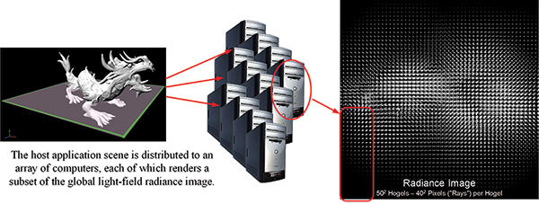
Fig. 5: In this distributed radiance image rendering, each render box renders a subset of the global radiance image.
Table 2 highlights the challenge of radiance image rendering for a 500 × 500 mm2 display consisting of 1mm2 hogels, comparing the number of render passes of both the double-frustum and oblique algorithms, and the number of red/green/blue (RGB) bytes rendered. While it is possible to reduce the rendering load by spatially and/or temporally subsampling rendered views or by tracking viewer head/eye position and orientation, these solutions can introduce additional artifacts into the light-field projection that degrade the visualization experience and, in some cases, inhibit collaboration. What should be obvious, though, is that light-field rendering is extremely parallelizable.
Table 2: Magnitude of radiance image rendering.
| |
Width Height |
| Display Size (1mm hogels) |
500 500 |
| |
Directional Resolution |
Single-Frustum Render Passes |
Double-Frustum Render Passes |
Oblique |
Total RGB Bytes |
| Low Resolution |
64 64 |
250,000 |
500,000 |
4,096 |
3,072,000,000 |
| Medium Resolution |
128 128 |
250,000 |
500,000 |
16,384 |
12,288,000,000 |
| High Resolution |
256 256 |
250,000 |
500,000 |
65,536 |
49,152,000,000 |
| Very High Resolution |
512 512 |
250,000 |
500,000 |
262,144 |
196,608,000,000 |
| Extreme Resolution |
1024 1024 |
250,000 |
500,000 |
1,048,576 |
786,432,000,000 |
Radiance Rendering Parallelization
There are two assumptions that preface the following discussion on radiance-rendering parallelization:
1. At the very least, the double-frustum render could be reduced to render both front and back frustums in a single pass of the geometry with a custom rasterizer. This results in a 2× hogels rendered per second (HPS) rate improvement (Table 2: SingleF column).
2. In a simple battle-space rendering test with a terrain mesh and Phong shading from a single light source, the render pipeline is either dispatch- or vertex-transform limited and not fragment-processing limited. This implies that the destination viewport size is not a primary factor for either double-frustum or oblique rendering rates.
a. For this double-frustum rendering test, mesh-terrain files were loaded into batched triangle strips complete with bounding volumes to enable visualization tests; the render rates in terms of HPS did not change significantly when double-frustum rendering 128 × 128 pixel hogels or 1024 × 1024 pixel hogels.
b. The majority of the light-field battlespace and medical applications depicted in movies have very simple lighting. While these scenes are currently fiction, they do foretell a use case/need where 3D spatial relationship is more important than rendering pixels with complex lighting and/or special effects.
Multi-GPU Parallelization: With Table 2 in mind, consider that if 20 GPUs are employed for radiance-image rendering, each owning render responsibility for an independent subset of the global radiance image, each GPU would have to render 12,500 (500 × 500/20) views in the optimized double-frustum render. The number of renders required by each of the 20 GPUs for oblique rendering would not change (each GPU would still have to render 500 × 500 views); only the size of the destination viewport would vary. As such, for example, the number of oblique-render views for the “medium resolution” radiance image in Table 2 exceeds the number of optimized double-frustum renders (16,384 > 12,500). In addition, the oblique-rendered radiance image would undergo a 614,400,000-(12,288,000,000/20) byte transform per GPU into hogel space before display.
Multiview Render Parallelization: The concept behind multiview render parallelism is to render as many views as possible per triangle dispatch. The ultimate goal is to responsibly relieve the host CPU from multiview rendering. This requires that a GPU-like device maintains a list of view transforms with corresponding viewports and applies any distortion corrections required by the optical system automatically within a specialized rendering pipeline.
One of the primary issues with multiview rendering across an array of GPUs is that the update rate of the host application becomes tied to the update rate of the multiview display. This occurs because the geometric definition of a scene cannot change during a display rendering cycle. If a multiview display rendering engine takes 10 seconds to render all views, then the host application rendering engine stalls for 10 seconds to preserve GPU cache integrity.
Once multiview rendering becomes the responsibility of the display using a GPU-like device, then the host CPU update rate is no longer dependent on the multiview renderer. Inessence, the host application becomes loosely bound to the update rate of the display as long as the GPU-like device maintains a list of geometry cache updates to be applied between render cycles. Light-field (multiview) rendering then becomes the responsibility of the “display,” and the host application has no knowledge or concern with regard to views being generated.
The Heterogeneous Display Environment
Decoupling the host application from the display enables the heterogeneous display environment (HDE) (Fig. 6). Within the HDE, the host application executes blindly without knowledge of the number or architecture of attached displays. Consider the previously described football game scenario in which a server is broadcasting an “e-sport” football game. The viewer should be able to watch the game on any display device, whether head-mounted stereo, volumetric, or light field. This scenario implies a few key concepts.
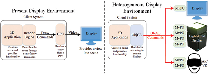
Fig. 6: The image on the left describes the traditional display environment in use today, while the right image shows a future Heterogeneous Display Environment where multiple displays/architectures are connected to a single application simultaneously.
The first is that the e-sport game broadcast consists of geometric model data and not prerendered pixels. Prerendered pixels imply a particular singular-view orientation that may not be conducive to all display architectures. For example, a prerendered view from the quarterback’s perspective is not conducive to generating a god’s-eye view for a light-field display. Likewise, the prerendered light-field field is way too many pixels (even compressed) to transport over existing (or future) networks to facilitate a first-person view for an HMD at a reasonable frame rate. In addition, prerendered pixel data is likely to result in poorly sampled visualizations or visualizations with noticeable occlusion artifacts if not displayed on the intended device.
The second idea is that the visualization device is allowed to select the appropriate viewpoint or view volume. This allows the viewer with the HMD to select a vantage point to watch the e-game, whether from the quarterback’s, receiver’s, or coach’s perspective. This implies that the geometric broadcast of the e-game is accompanied by a number of predefined interesting viewpoints/view volumes and that the viewer can switch between them at will.
The third concept is that the displays can connect to the host application broadcast at any time, which means that upon receiving geometric render commands, the display’s geometric cache is likely to be stale. Therefore, out-of-band displays require a mechanism to request geometric updates from the host application’s geometry server. These geometric “updates” are broadcast to requester and not globally to the HDE.
Multiview Processing Unit (MvPU): The primary technical objective of the multiview processing unit (MvPU) is to reduce the size, weight, power, and cost (SWaP-C) of multiview rendering by developing a processor capable of rendering multiple views in parallel without the need for a cluster of off-the-shelf (OTS) computers. By removing the OS, CPUs, and other PC system components, and refactoring the traditional graphics pipeline to render multiple views in parallel, a more efficient light-field/multiview rendering engine can be developed (Fig. 7).
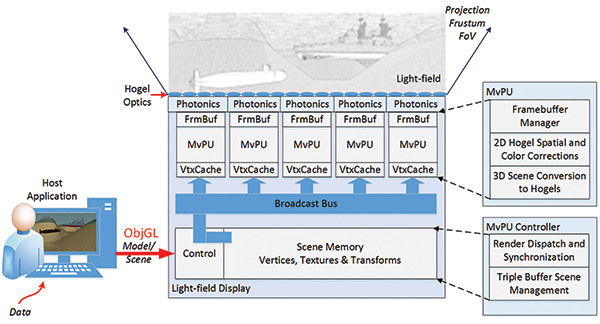
Fig. 7: MvPUs within the light-field display: An MvPU controller is responsible for managing the scene while the MvPU rasterizer converts triangles into pixels directly into the modulation framebuffers.
Since many (possibly 10s to 100s) MvPUs may be required to drive a single light-field display, it is important that the MvPU be an independent processor, requiring minimal support logic and interconnect. Ideally, neither the host system nor the individual MvPUs would have knowledge of the interconnect topology or even the depth and breadth of the multiview system. The MvPU interconnect framework would provide scene, command, and sync buffering and relay throughout the topology.
The MvPU is physically located in close proximity to the photonics subsystem and has direct write access to the modulation driver back buffers. This reduces the complexity of the MvPU interconnect/support framework and eliminates the need to compress/transfer/decompress pixels from the render source to the destination driver over long traces/paths.
Each MvPU hosts multiple parallel independent render pipelines, which are fed viewpoints to be rendered simultaneously as triangles are dispatched. Dispatched triangles are transformed according to their unique viewpoints and are likewise shaded. Spatial distortion and color corrections complete the backside of each rendering pipeline.
Object Graphics Language (ObjGL): Object Graphics Language (ObjGL) is conceived by FoVI3D as an application- and display-agnostic API where rendering is the responsibility of the display. ObjGL draws heavily from the popular OpenGL graphics language yet is streamlined and optimized for fast rendering for remote multiview systems. The ObjGL API is simple and efficient, and it provides many geometric rendering clues that can be exploited by a well-implemented multiview rendering system.
The ObjGL application interface consists of three types of instructions: Control, Cache, and Render. Cache and Render instructions cannot be mixed and are delineated by Control commands. By strictly identifying Cache and Render commands, the multiview render system can accumulate Cache commands while executing its render cycle. After the multiview render cycle is complete, the Cache commands can be applied and the next complete render frame executed. This effectively allows for multiple displays to update independently while rendering the same content.
To support accelerated multiview rendering, a number of constructs and constraints are being developed to simplify the geometry definition yet provide efficient mechanisms for fast multiview rendering. These constructs/constraints are typical of the operations that intelligent rendering systems implement in software yet are propagated to the multiview display for implementation. In many cases, these constructs can’t be applied within the host application, since the multiview rendering needs (points of view, display transform matrices, viewports, etc.) of the display are unknown to the host application. Some of these acceleration constructs include:
• Bounding volumes
• Foreground/background geometric segmentation
• Geometric level of detail
• Criticality of objects
• Frame packing
• Data phasing
ObjGL Thread Model: The ObjGL thread model is shown in Fig. 8 and consists of two primary threads, the application thread in which the application executes and the ObjGL manager thread. The ObjGL manager receives ObjGL commands from the host application, caches the geometry messages into a local message database, and formats the commands for global broadcast to all attached displays. In addition, the ObjGL manager receives out-of-band requests for late-joining displays and specifically updates those requestors.
ObjGL is currently in development at FoVI3D and has been demonstrated with multiple Oculus and Vive HMDs, and real and simulated light-field displays simultaneously viewing 3D imagery from multiple perspectives. FoVI3D intends to release ObjGL to the greater open-source community within the next year once the base architecture has been validated.
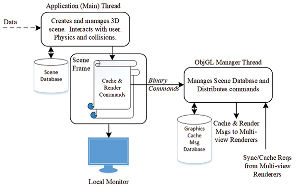
Fig. 8: This ObjGL thread model highlights the separation of application and ObjGL scene-management responsibilities.
Computation Solutions Are in the Making
Light-field displays are no longer just a science fiction concept, and a few companies are producing impressive light-field display prototypes. While the focus has been primarily the development of light-field photonics and optical solutions to preserve 3D aerial image fidelity, ultimately light-field computation is the barrier to deployment. The sheer number of pixels required to produce high-fidelity light-field content for a reasonable SWaP cost is daunting; however, light-field computation is not an unsolvable problem. Light-field computation is highly parallelizable, and there are modes of operation and geometric model/scene properties that can greatly accelerate light-field rendering.
FoVI3D has developed a new system architecture to address the SWaP cost of light-field/multiview rendering. This architecture requires two major new elements that are in development at FoVI3D. The first is a multiview processing unit (MvPU), a GPU-like device designed to render multiple views in parallel without support from the host application. The second is an object-oriented graphics API Object GL (ObjGL) designed specifically to offload rendering to a heterogeneous display environment where rendering is the responsibility of the display. The successful completion of these two projects will enable graphical content to be remotely generated and transmitted for rendering at the display device whether it is a head-mounted stereo, volumetric display, or light-field display.
Eventually, this capability will enable a game to be captured (or generated, as in e-sports) and distributed to a home where a group of friends can enjoy a light-field 3D aerial projection of the game without head-gear or eyewear inhibiting their personal interactions. This is a true 3D vision of the future.
Acknowledgements
FoVI3D would like to recognize the support that the Air Force, Navy, and Army SBIR programs have contributed to the advancement of light-field display technology. In particular, the Air Force HVD & FMHDb programs are advancing the LfD optics and photonics; the Air Force SMFoLD and the Navy ObjGL & LfPU (MvPU) programs address multiview rendering for Field of Light Displays (FoLDs); and the Army SCBV program advances the manner in which 3D aerial content is projected to reduce the cognitive load on the viewer.
References
1M. Hackett, “Medical Holography for Basic Anatomy Training,” Interservice/Industry Training, Simulation and Education Conference (I/ITSEC), 2013.
2S. Fuhrmann et al., “Investigating Geospatial Holograms for Special Weapons and Tactics Teams,” Cartographic Perspectives, 2009.
3M. Klug et al., “A Scalable, Collaborative, Interactive Light-Field Display System,” SID Symposium Digest of Technical Paper, 2013.
4N. Balram, “Fundamentals of Light-Field Imaging and Display Systems,” Short Course, Display Week 2016.
5M. Halle and A. Kropp, “Fast Computer Graphics Rendering for Full Parallax Spatial Displays,” Massachusetts Institute of Technology, Media Laboratory, Cambridge. •
As the software lead at Zebra Imaging, Thomas Burnett was a key contributor in the development of static light-field topographic maps for use by the Department of Defense in Iraq and Afghanistan. More recently, he launched a new light-field display development program at FoVI3D, where he serves as CTO. He can be reached at tburnett@fovi3d.com.
_________
a
In a previous article, we had referred to this measurement as angular resolution. Angular Pitch is a better descriptor. Angular resolution would be better defined as
Dr/FoV
.
_________
bWith support from NavSea.