Calibration Requirements for Demanding Measurement Challenges
Calibration Requirements for Demanding Measurement Challenges
Calibration Requirements for Demanding Measurement Challenges
Today’s state-of-the-art displays, with their wider dynamic ranges and larger areas, demand state-of-the-art measurements. Those measurements must start with accurate calibration sources. The author offers two new designs for light sources geared toward wide-angle and low-luminance calibrations.
by Edward F. Kelley
AS displays continue to evolve in terms of size and wider dynamic range – “brighter” brights and deeper blacks – they are straining the limits of our measurement capabilities, particularly in the dark regions. Companies may possess the tools to perform the required optical measurements, but these tools must be calibrated using suitable standard sources to produce accurate results.
In the case of large displays, for example, many companies use various cameras and imagers to capture the entire surface of the display at one time for analysis. But with large displays and a camera placed at a close viewing distance, there is the problem of providing a calibration that supports the wide-angle lens and image field to be measured – often referred to as a flat-field correction. That is, we want the response of the camera to be uniform for all angles it observes. To make such a calibration, a uniform source of light over that wide angle, as described here, is necessary.
A second challenge involves the very dark blacks – even zero-luminance blacks – that the newest displays are now able to produce. We need to be sure our measurement instrumentation is sensitive enough at those very low light levels. Can what we are using really measure as low as we need it to measure, and be linear at those levels? Once again, an adjustable low-luminance source of light is the key. To perform such calibrations and checks of linearity, we need a well-characterized source of light down to the limits of human sensitivity. A dual-sphere source is described herein to provide such a source of light.
Uniform Source for Wide-Angle Lenses
The first design addresses the issue of measuring large displays. Often cameras or tristimulus imagers are employed to characterize the uniformity of such displays. To calibrate such wide-angle devices, a uniform source over 180° can be very useful.
Some integrating spheres exist that can accommodate such wide-angle calibrations, but they tend to be larger. Figure 1 shows the author’s solution in a cut-away view of the uniform source with a transmissive-diffusing, slightly flattened, flanged dome at the exit port. The interior diameter of this sphere is 229 mm (9 in.) yet the exit port is almost 152 mm (6 in.). Normally, the maximum exit port size is one third of the sphere diameter or less to assure a 1 percent uniformity; this one is two-thirds the diameter.
The dome is made of white plastic acrylic that serves as a transmitting diffuser. It is sandblasted on both sides to make its surfaces diffusing as well. Nonuniformity is avoided by ensuring that any ray from the source cannot strike the dome directly. Thus, a baffle of sufficient diameter is installed ahead of the source that prevents lamp rays from hitting the dome. This baffle is mounted on a transparent polymethylmethacrylate (PMMA) sheet. An iris can be used to regulate the luminance of the dome. A 12-V Soraa 5,000-K
light-emitting-diode (LED) lamp is used to provide a broad spectrum, and a 12-V fan draws air from in front of the lamp to keep it cool, below 30 °C. A 40 °C thermal switch (not shown) is placed against the base of the lamp to turn it off should the fan fail. The entire apparatus was prototyped on a 3D printer and could be reproduced this way.
Also shown in Fig. 1 at the bottom left is an alternative way to mount the baffle on a semi-transparent holder that fits within the hole for the lamp. The sphere interior and baffle are painted with several coats of white interior latex paint. A better coating material would be barium sulfate, of course, because of its higher reflectance and more uniform spectral reflectance.
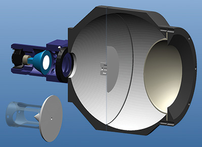
Fig. 1: A cut-away view of the uniform source shows a sphere with an interior of 229 mm (9 in.) and an exit port that is almost 152 mm (6 in.). An alternative baffle is shown at bottom left.
Note that the flange that holds the dome in place has a smaller diameter than the inner diameter (ID) of the dome. The face of this flange that faces the dome is white, and that provides a small amount of illumination on the interior of the dome next to the flange. This is done to improve the uniformity at very large angles from the normal of the dome. However, if we increase the exit-port diameter 10 mm or more with the same-sized dome, the region near the flat-flange of the dome will then be better illuminated by the sphere interior and can permit a flange of the same inner diameter (ID) as the ID of the dome.
Figure 2 shows the normalized luminance uniformity of the dome as a function of angle around the center of the exit port from the normal of the dome. This data was obtained with a spectroradiometer placed some distance away from the dome, and the entire source structure was rotated about the center of the exit port to obtain the data. There is a maximum deviation from the central value along the normal of approximately 2 percent at the right side and top. We thus have a source that could be used to obtain a flat-field correction for even a fish-eye lens.
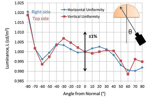
Fig. 2: Dome luminance uniformity vs. angle from the center normal line of the dome appears in terms of horizontal (blue) and vertical (red) uniformity.
This uniform dome is only useful for lenses placed just inside the dome. It is not useful for cameras with lenses placed some distance from the exit port. This is because the interior surface of the dome is only quasi-Lambertian. When a lens is just inside the dome, the rays entering the lens at wide angles are nearly perpendicular to the surface elements of the interior of the dome. But when the lens is a distance away from the exit port, the rays near the edges of the dome that are directed toward the lens are at a large angle to the interior dome surface, and the imperfect Lambertian surface renders such light darker than at the center of the dome. To allow this device to be used with cameras at a distance from the exit port, one would replace the dome with a flat, white, acrylic-plastic disk that is also sand-blasted on both sides. It is not possible to use this source without a diffuser at the exit port because the baffle is considerably smaller than the diameter of the exit port.
Research is under way to improve the design and attempt to make the device smaller using a 150-mm (6-in.) sphere with a 100-mm (4-in.) exit port. Attempts will also be made to eliminate the white region on the interior of the flange by modifying the internal shape of the sphere in the vicinity of the exit port.
Dual-Sphere Source for Low-Luminance and Linearity Testing
The second design addresses the problem of measuring displays with very deep blacks. There is an entire section in the International Display Measurements Standard (IDMS) that covers making low-light measurements and testing.1 Of course, to do those measurements you need a uniform source of light in the same order of magnitude of the luminance you intend to measure. This is hard to achieve with typical sources: Just turning down the power to the light source lamp isn’t adequate because the spectrum of the lamp may vary too much with power level, and mechanical reductions using apertures can produce insufficient light distribution into the sphere to permit a reliable calibration of the sphere. One of the recommended methods to create low-light sources is to use two integrating spheres (see IDMS, p. 420). This kind of arrangement is employed here, with some improvements.
The main improvement shown in Fig. 3 is a stray-light-elimination tube (SLET) that is placed between the first sphere (#1), the source sphere, and the second sphere (#2). Sphere #1 can be calibrated either by rotating it away from the SLET or removing it entirely from the apparatus. The calibration of sphere #1 is made using a spectroradiometer or luminance meter to obtain the relationship between the photopic photodiode current J and the luminance L1 of the sphere #1. The lamp on sphere #1 is a fan-cooled LED. The luminance can be changed by changing the LED current, by an iris, or both. After calibration of sphere #1, it is replaced against the SLET. The advantage of the SLET is that it prevents any back reflections from sphere #2 into sphere #1. Preventing any stray light from entering sphere #1 from reflections is important to maintaining the L1(J) calibration relationship when sphere #1 is positioned up to the SLET. Sphere #1 has an extension between the two sphere halves that greatly decreases the nonuniformity of the baffle in sphere #1 to approximately 0.1 percent. This reduces any aiming sensitivity in L1 measurements.2
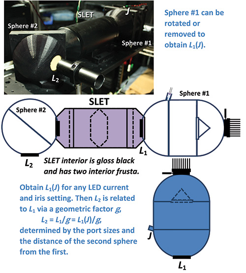
Fig. 3: This dual-sphere source prototype is designed for more accurate measurement in very low light levels.
Light from the exit port of sphere #1 travels through the SLET and into sphere #2. Thus, there should be a linear relationship between L2 and L1 based upon a geometrical factor g. To calibrate that factor, we make L1(J) as large as possible and measure the luminance L2. Thus, g = L1(Jmax)/L2, and for this prototype apparatus we find that g = 1,060 with an uncertainty of 10 percent (coverage factor of two) for L1 above 1 cd/m2 (for lower light levels, the uncertainty in g increases because of various factors discussed below). It is possible to monitor the photodiode current with a good picoammeter and then predict L2 based upon the photocurrent J. However, to reliably reach and control the light in the realm of the limits of human vision of Lrods = 3 × 10⁻⁶ cd/m2, we would need to make sphere #1 have a luminance of L1 = 0.003 cd/m2.3 It is possible to reach Lrods with this prototype apparatus by looking at the exit port of sphere #2 using dark-adapted eyes and averted vision, but because of the increase in the uncertainty of our measurements at these levels, the L2 accuracy may be compromised.
A new dual-sphere apparatus is being designed in order to make the low-light realm in the vicinity of Lrods more reliable than the prototype apparatus in Fig. 3. The present apparatus shows changes in the apparent geometrical factor g on the order of tens of percent in L2(J) with the iris almost closed and LED current reduced, providing sufficiently low levels of light in sphere #1. Since the spectrum from the LED changes with drive current, it is not a good idea to change that current (after initial calibration). Using apertures and an iris in a new apparatus design will be required. Any change in g with the iris diameter in the present apparatus probably has to do with changes introduced in the light distribution by the photodiode not confining its monitoring to the light on the baffle and using light from the interior wall; the new apparatus will correct this. To increase the geometrical factor g so that Lrods can readily be reached and controlled well in sphere #2, the apertures on each side of the SLET must be reduced, but in order to calibrate that factor, we will need more light in sphere #1. It is anticipated that a photopic-photomultiplier-tube detector will be needed to monitor L2 in the region of Lrods. These changes will be made in the future and published in the open literature.
Why is it important to have a source that can reliably reach the limits of human low-light vision? If we want to measure just how black the new displays can get, we need an adjustable calibration light source that can provide those levels and not only check the measurement accuracy of any detector but also its linearity in that low-light region. Only then can we be sure of reliable black measurements.
Both of the above integrating-sphere-based instruments are offered to the display industry and placed in the public domain – no patents or licensing to impede their implementation. I hope these designs will be useful – consider them part of my swan song (I’m almost 70 years old).
References
1International Committee for Display Metrology of the Society for Information Display, Information Display Measurements Standard (IDMS) version 1.03, appendix A3.
2E. F. Kelley, A. Dowd, A. Fong, R. Bronson, B. Goodman, “Ultra-Uniform Oblong Integrating Light Source,” paper P-64, Society for Information Display International Symposium Digest of Technical Papers, pp. 1375–1376, 2016.
3R. E. Miller and T. J. Tredici, Night Vision Manual for the Flight Surgeon, Ophthalmology branch, Armstrong Laboratory, Human Systems Center (AFMC), Brooks Air Force Base, TX 78235-5000, AL-SR-1992-0002 August 1992. They state, p. 9, “The dimmest light in which rods can fuction is about 10–6 millilambert …. This illumination is equivalent to ambient conditions of an overcast night with no moonlight. The dimmest light in which the cones can function is about
10–3 mL.” To convert to luminance levels, 1 lambert = 1 L = 3183.1 cd/m2. Thus 10–6 mL or 10–9 L = 3.2 × 10⁻⁶ cd/m2. •
Edward F. Kelley is the founder of KELTEK, LLC (http://keltekresearch.com). He can be reached at ed@keltekresearch.com.