Two New Technology Developments in the LCD Industry
Flat-panel-display manufacturers are looking for ways to extend the display market. Besides increasing the size and improving the image quality of displays, new functions can provide additional applications for the product. Among the new technologies currently being implemented and investigated are 3-D and in-cell touch.
by Jenn Jia Su, Hsiang-lin Lin, and Alan Lien
FLAT-PANEL-DISPLAY (FPD) technology has seen many exciting developments over the past decade, and among these liquid-crystal-display (LCD) technology has risen to the top. Today, countless electronic devices use LCDs to display vital information and to provide entertainment. LCD manufacturers are continuously investing in larger-generation factories to increase the average size of displays. And at the same time, many revolutionary technologies such as new LC modes, pixel structures, and manufacturing processes have been developed to further improve image quality.
New demands from consumer are helping to drive the development of the next generation of displays. For example, film directors have immersed their audiences in the scenes of movies by using 3-D technology. The consumer enjoys the 3-D experience and wants to watch 3-D TV at home (or 3-D TV manufac-turers hope so). With regard to touch, the iPhone provides a very convenient and reliable user interface, and displays embedded with touch functionality will be a standard in the future.
1. 3-D LCD Technology
To enable 3-D viewing on a flat-panel display, the basic concept is to allow the right eye to see the right image and the left eye to see the left image. Several technologies have been developed to achieve this, as shown in Fig. 1.
The 3-D technologies are classified into two categories based on whether or not users need to wear glasses.
1.1. Glasses-Based 3-D Technology
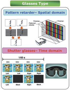
There are two types of 3-D technology that require users to wear glasses, as shown in Fig. 1(a). The first involves a patterned retarder; the other, shutter glasses. Patterned-retarder technology is based on the spatial-domain concept.1 The content of the left and right views are rearranged in an interlaced pattern that loses 50% of the information of each view. On the display side, an additional retardation film with a striped pattern is placed in front of the base of the panel. The retardation film is used to change the polarization of the light coming from the base of the panel. The striped pattern is designed to have a phase difference of λ/2 between the odd and even rows. Lastly, a pair of unpowered passive glasses composed of polarizer film is used to filter the corresponding image for each eye.
(a)
(b)
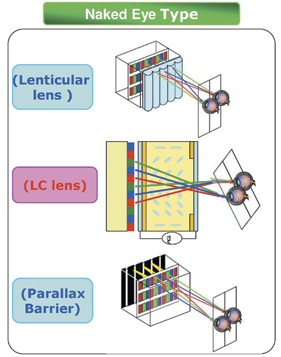
Fig. 1: Hardware configurations used for 3-D technologies, both (a) with and (b) without the use of glasses, are depicted above.
Shutter-glasses technology uses the time-domain concept.2 The content of the left and right views vary with time. The content must be synchronized with the shutter glasses in order for the corresponding images to be seen by each eye. On the display side, the display must be designed to support a higher-frame-rate driving capability. Furthermore, the response time of both the display and the glasses must be as fast as possible in order to obtain acceptable 3-D performance.
The merits and drawbacks of these two technologies are as follows:
• Glasses: The patterned-retarder method utilizes passive glasses, composed of polarizer films. They are lightweight (<10 g), cheap (<US$10), and easy to clean. The shutter-glasses method uses active glasses that are composed of two LC cells that are driven by batteries. They are heavy (~50 g) and more uncomfortable to wear. They are also expensive (~US$100) and difficult to clean with water.
• 3-D luminance: Both current 3-D approaches represent a significant sacrifice in total luminance available to the observer. For the patterned-retarder method, the combined effect of the retarder on the display and the polarizer film on the passive glasses results in a net loss in luminance of about 58%. Approximately 50% is due to the inherent separation of the 2-D image into separate left and right fields. The polarizer film on the glasses, which is made with a polyvinyl alcohol (PVA) plastic layer, absorbs another 16% of the light that tries to pass through it, resulting in a net transmission of 50% times 84%. Therefore, the maximum 3-D luminance for the patterned-retarder method is 42% of that for the 2-D mode. However, higher 3-D cross-talk can be perceived at large vertical viewing angles in current patterned-retarder structures. To solve this problem, an additional black-matrix (BM) layer or equivalent pixel structure is used, which leads to a further loss in luminance of 40%. As a result, the final transmittance of the 3-D imagery is about 25% of that of 2-D imagery [based on an AU Optronics Corp. 65-in. full-high-definition (FHD) unit]. For the shutter-glasses method, the technology is based on time domain, and the blinking (shutter-open) ratio of each eye is only 25% at a 240-Hz frame rate. The glasses, which are composed of two polarizer films and one LC layer, have a transmittance of about 60%. The final transmittance of the shutter-glasses method in 3-D mode is about 15% of that of the 2-D imagery. Taking a 65-in. FHD TV with a 2-D-mode luminance of 500 nits as an example, the patterned- retarder method provides 125 nits in 3-D mode while the shutter-glasses method provides only 75 nits. (Typically 300–500 nits are preferred for an enjoyable viewing experience. However, since the 3-D mode always offers lower luminance, a luminance of 125 nits definitely provides better viewing performance than 75 nits.)
• 3-D cross-talk: Cross-talk is an index that defines the percentage of light leakage from one eye's image into the other eye's image. It identifies what percentage of the left view is perceived though the right eye, for example. The display with lower 3-D cross-talk provides a sharper image for each eye and increases viewer comfort when viewing 3-D content. For the pat-terned-retarder method, the cross-talk can be less than 1% by using an optimized design for both the retardation film and the glasses. For the shutter-glasses method, the response time of the display and glasses is a key parameter for cross-talk. In general, the shutter-glasses method results in more cross-talk than the pattern-retarder method.
• 3-D resolution: The shutter-glasses method has a major advantage in resolution because it is operated by the time domain, using all available display pixelsfor each eye image. The patterned-retarder embodiment loses one-half of the resolution in the vertical direction when operated in 3-D mode because the available pixels on the display are physically sorted into left or right eye images only. This should barely be detected by a user who is viewing imagery from a distance. However, if the contents have fine patterns such as text, a user can detect the loss of information very easily. The resulting user experience is therefore more content and viewing-position dependent.
1.2: "Naked-Eye" 3-D Technology
The 3-D technologies that work with the "naked eye" (no glasses) are based on the spatial domain and are also generally referred to as autostereoscopic. There are three types of autostereoscopic 3-D technology, as shown in Fig. 1(b). For the lenticular-lens type, a lenticular-lens film is placed in front of a flat-panel display to refract the image signal of each set of subpixels to specific positions in space. The best 3-D viewing distance is related to the design of the lens curvature and lens pitch. The LC-lens type is based on the same theory as the lenticular-lens type. The major difference is that the lens structure is composed of a liquid-crystal layer. A special electrode pattern is designed to align the liquid crystal that forms the effective refractive-index profile to have the same effect as a lenticular lens. For the parallax-barrier type, a black-matrix layer or another liquid-crystal layer is stacked with the FPD to block a portion of the output light and direct the image of the subpixel set to specific positions in space.
The image content of autostereoscopic 3-D technology requires simultaneous multi-views. In Fig. 2, the process flow from five different images into a single 3-D image is illustrated.
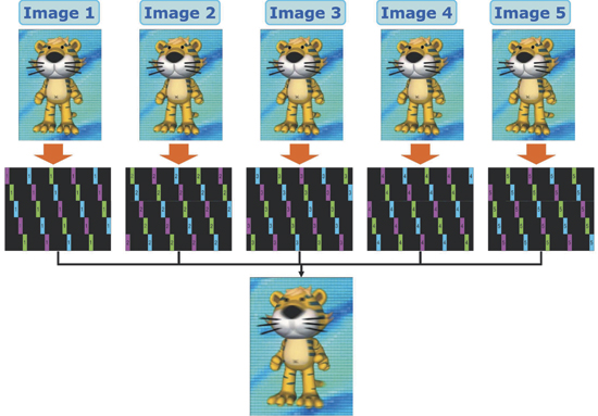
Fig. 2: For the signal arrangement of multi-view 3-D displays, the output image is the combination of the five images with special pixel arrangements.
These five images are captured by a charge-coupled device (CCD) at a slightly different viewing angle. The length of the tiger's tail in each view is therefore slightly different. The combination of the five images into a single one is processed through a special subpixel-arrangement method. The subpixel arrangement in each view must correspond to the structure of the lenticular lens or parallax barrier. As a result, the final 3-D content includes all five images, and thus 80% of the information of each view is lost.
By using a combination of multi-view content and an autostereoscopic display, viewers can see the combined 3-D image from a specific position in front of the display. They will also see some dead zones from other positions. To reduce the number of dead zones, 9 or 12 views are required. However, 89% or an even higher percentage of the resolution will be lost, which degrades the image quality dramatically. To improve the 3-D image quality, an FPD with a higher resolution (4K x 2K or 8K x 4K) is required, which is challenging for LCD designers and manufacturers.
1.3. The Future of 3-D Technology
Consumers are looking for high-quality 3-D technology and hoping to enjoy the 3-D experience more comfortably. In the short term, glasses-type 3-D displays will dominate the market because it currently provides the best image quality. In terms of 3-D cross-talk, the shutter-glasses type needs to be improved by using a faster-response-time FPD or a higher-frame-rate LCD. The synchronization between the content and the blinking time of the glasses can also reduce the cross-talk. The shutter glasses should be designed to be lighter in weight and will get less expensive in the future. For the patterned-retarder type, the LCD makers are eager to reduce the cost of the retardation film. A 50% lose in resolution and a limited vertical viewing angle are still the challenging issues that need to be addressed. In the long term, the naked-eye-type 3-D technology is undoubtedly the best 3-D solution. Large-sized displays with resolutions higher than FHD is now quite challenging because of low cell transmittance. However, 3-D capability will be a key force driving the development of higher-resolution displays in the future.
2. In-cell-Touch LCD Technology
Displays with touch functionality are in great demand (as explained in other recent articles in Information Display, and especially in our March 2010 issue). At the current time, touch sensors are mostly integrated outside of the display, and we call this an "out-cell touch display." These technologies include projection-capacitance, resistor, motion sensor, IR sensor, etc. However, it is an industry goal that the touch sensors be integrated into the LCD cells, which we call "in-cell touch displays." This technology provides the merits of (a) reducing the total thickness of the module, (b) reducing the light-interference effect due to the additional touch-screen glass, (c) not requiring calibration between the LCD and the touch sensors, and (d) providing the possibility of lower overall system cost.
Figure 3 summarizes the four types of in-cell touch technology that have been recently developed. The first type is a photosensor3using ambient light. Compared to a conventional TFT-LCD, a matrix of additional TFTs is designed on the array side of the display. On the color-filter side, the black-matrix layer of these additional TFTs is removed. As a result, these TFTs have leakage currents if they are placed in a bright environment. The leakage currents from these TFTs are conducted to the integrated-circuit chips by the readout lines, which are also designed on the array side. If the user places a finger in front of the display, it will obstruct the environmental light radiating to these TFTs, and the TFTs will stop leaking currents to the readout lines. The integrated-circuit chips will compare the voltage differences of each readout line and judge the position of the finger. Obviously, the environmental light will affect the operation of the touch function. To increase environmental flexibility and allow the technology to work in a dark-ambient environment, additional illumination such as infrared light can be added to the system, provided either by the backlight or from a front-light enhancement.
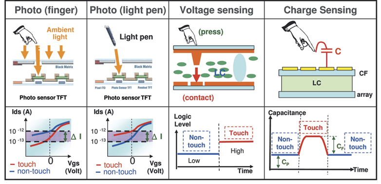
Fig. 3: Summary of in-cell touch technologies, with both the structure profile and the signal transition with and without touch are described above. Note: The fourth technology, charge sensing, is sometimes referred to as "on-cell" technology, depending on the configuration. For more on this distinction, see the article "LCD In-Cell Touch" in the March 2010 issue of Information Display.
The second technology is also based on the photosensor method described for the first case. The only difference is that the user points at the display by using a light pen. As a result, the TFTs leak more current when the TFTs are exposed to the light. The position pointed to by the user can be detected by the readout lines and integrated-circuit chips.
The third technology is the voltage-sensing type.4 It involves a matrix of sensor pads that are designed in the array substrate. The sensor pads are made with metal electrodes or transparent electrodes such as ITO and are located on the top layer of the array electrode, which will be used to make contact with the color-filter layer directly. To prevent the sensor pads from covering polyimide, a special sensor-pad design is used. On the color-filter side, two photo-spacer processes are required. The first photo-spacer layer is processed after the color-filter resin layers. The common electrode layer is then deposited on the surface of the color-filter resin and the first photo-spacer layer. The second photo-spacer layer is then processed, which will be used to maintain the cell gap of the LCD. The height of the first photo-spacer layer is slightly smaller than the second photo-spacer layer. When there has been no touch force applied to the display, the cell gaps are maintained based on the second photo-space layer. However, if the panel is pressed with a certain force, the cell gap is reduced and there will be direct contact between the common electrode in the color-filter layer and the sensor pads in the array substrate. The voltage of the common electrode is then transmitted to the integrated-circuit chips by the readout lines that are linked to the sensor pads. The integrated-circuit chips calculate the logic level between touch and non-touch; therefore, the position in which the user applies force on the display can be detected. Unlike the photo-sensing method, this technology is independent of the brightness of the environment. It has the potential to detect pressure through a special sensor-pad design. There are many good features for this kind of technology, such as low cost and high cell transmittance. However, the biggest challenge is that the user needs to apply significant pressure to trigger the sensors. The force is called activation force, which is an index of the sensitivity of the touch function. To reduce the activation force, the thickness of the color-filter substrate should be polished to less than 0.2 mm; however, that will cause low yield in the LCD process. (Although touch-panel durability is not covered in this article, it is worth noting that for touch-display applications, the panels will be tested for durability with more than 500,000–1,000,000 repeat contacts. Suitable photo-spacer materials and designs can help touch-panel products meet durability requirements.)
The fourth technology is charge-sensing touch-display technology. The design of the pixel on the array and color-filter sides is the same as that for conventional LCDs. On the outside of the color-filter substrate, there is a matrix of sensor pads made by transparent electrodes such as ITO. All of the sensor pads are linked to the integrated-circuit chips. If a finger is placed on the surface of the display, there is additional capacitance between the sensor pads and the finger. The integrated-circuit chips detect the change in the capacitance of the sensor pads and then determine the position of the finger. This technology has the features of high sensitivity, high transmittance, and low cost. The major concern is the dual-side color-filter process, which may suffer scratches in the electrode layer.
2.1. Future Perspective of In-Cell Touch Technology
More and more operating systems will support displays with touch functionality as an input interface. There are also numerous technologies that can provide touch functionality. In-cell touch technology has many good features, such as thinner modules, low cost, and good image quality. It should be very suitable for small-sized LCD or portable applications. All the technologies described above support multi-touch features (at least two points), which are useful for practical applications. In the short term, there are some aspects that need to be improved for in-cell touch technology: (a) the frame rate of the sampling touch sensors should be faster (>180 Hz) in order to catch up with the high speed of handwriting, (b) the yield must be improved, and (c) the sensitivity of the touch function should be as good as the projection-capacitance type. But there should be no limitation in terms of input devices. And in the long term, a touch display should be able to detect the depth information based on the activation force of the user.
3. Summary
Nowadays, most technologies need to combine both software and hardware in order to meet consumer requirements. For 3-D technology, the display needs to provide good-quality 3-D imagery without sacrificing 2-D imagery. Despite the inconveniences, glasses-type technology seems to be the best solution thus far. Besides, the availability of high-image-quality 3-D content is also a key factor in the success 3-D displays in the future. For touch technologies, there are a variety of solutions, but in-cell technology provides many good features for which LCD manufacturers are keen on developing it for mass production. Because the FPD industry is a consumer-oriented industry, these technologies along with other technologies are being developed to meet consumer requirements.
References
1Y-J. Wu, et al., "Stereoscopic 3-D Display Using Patterned Retarder," SID Symposium Digest 39, 260-263 (2008).
2S. S. Kim, et al., Invited Paper: "World's First 240-Hz TFT-LCD for Full-HD LCD-TV and Its Application to 3-D Displays," SID Symposium Digest 40, 424-427 (2009).
3B. H. You, et al., "A New Touch-Sensitive Active-Matrix Display with Embedded Light Sensors," Proc. IDW '08, AMD 6-2, 1605-1608 (2008).
4H-S. Park, et al., "12.1-in. a-Si:H TFT-LCD with Embedded Touch-Screen Panel," SID Symposium Digest 39, 830-833 (2008). •
Jenn Jia Su is Senior Manager of the LC Technology Department at AU Optronics Corp., located in Hsinchu Science Park, Taiwan; e-mail: potato.su@auo.com. Hsiang-lin Lin is the Manager of the Flexible Technology Department at AU Optronics Corp.; e-mail:Stan.HL.Lin@auo.com. Alan Lien is currently a Senior Associate Vice President in charge of the Display Development Center of AU Optronics Corp.; e-mail: alan.lien@auo.com.