Journal of the
SOCIETY FOR
INFORMATION
DISPLAY
A preview of the papers appearing in the January 2007issue of the Journal of the SID. To obtain access to these articles on-line, please go to www.sid.org
Edited by Aris Silzars
Novel pixel design for high-resolution AMOLED displays with a shadow mask
Jiin-Jou Lih
Ching-Ian Chao
Chung-Chun Lee
AU Optronics Corp., Taiwan, R.O.C.
Abstract — The bottlenecks in achieving high resolution for active-matrix OLED (AMOLED) displays based on currently available manufacturing processes were evaluated and compared. The use of a shadow mask has proven to be viable for mass production, but the fabrication of high-precision shadow masks becomes very difficult when the resolution exceeds 180 ppi. The latest breakthrough in increasing display resolution is presented. Without an increase in cost, the limitations of the conventional shadow-mask process using novel subpixel designs have been successfully overcome. A high resolution reaching 270 ppi has been successfully demonstrated on a 3-in. VGA-format AMOLED display, fabricated by using a shadow mask with a much lower resolution of 135 ppi. This innovative pixel design opens up the possibilities of manufacturing high-resolution displays using a relatively low-resolution shadow mask.
The shadow-mask process is a currently available manufacturing process used for volume production. The process ensures that the OLEDs can emit RGB light without the need for further conversion or filtering, resulting in virtually no loss in energy. Therefore, the advantages of low power consumption, high color saturation, long lifetime, and lower cost make it a popular technology in the manufacture of full-color AMOLED displays. However, a high-precision shadow mask has a physical limitation in not being able to provide mask openings smaller than 50 μm (Fig. 1). Because high resolution is a requirement for small-sized displays, this hampers the use of shadow masks in the manufacture of high-resolution AMOLED displays.
|
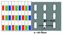
FIGURE 1 — The conventional pixel design of a full-color OLED display and the corresponding shadow mask used for individual colors are shown.
|
Progress in flexible and drapable reflective cholesteric displays
Asad Khan, Irina Shiyanovskaya
Tod Schneider, Erica Montbach
Donald J. Davis, Nick Miller
Duane Marhefka, Todd Ernst
Forrest Nicholson, J. William Doane
Kent Displays, Inc., U.S.A.
Abstract — Recent results from encapsulation work on the development of flexible and drapable cholesteric liquid-crystal displays (LCDs) on substrates such as thin plastics, fabrics, and even paper will be presented. The approaches used to create flexible displays using single- and dual-substrate methods based on printable emulsions and polymerization-induced phase-separation (PIPS) techniques will be discussed.
We have recently developed ultra-thin PIPS-based cholesteric displays on polymeric substrates that are only 50 μm thick. This makes the total display thickness to be only slightly over 100 μm. This thin display is highly flexible yet rugged. New edge sealing mechanisms further ruggedize the display against delamination. Figure 3 shows photographs of PIPS displays on plastic substrates. Figure 3(a) shows a segmented display that is flexible, while Fig. 3(b) shows a pixilated QVGA (240 ´ 320) display that is in a fixed curvature, illustrating its use on the arm of a soldier. The electronics behind the display are also curved to create a slim-profile design to conform to the curvature of an arm.
|
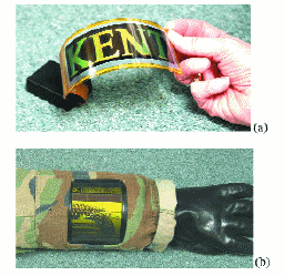
FIGURE 3 — PIPS-based displays on plastic substrates showing (a) flexing of a segmented display and (b) fixed curvature in a pixilated QVGA display (240 ´ 320).
|
Novel top-gate zinc oxide thin-film transistors (ZnO TFTs) for AMLCDs
Takashi Hirao, Mamoru Furuta
Hiroshi Furuta, Tokiyoshi Matsuda
Takahiro Hiramatsu, Hitoshi Hokari
Motohiko Yoshida, Hiromitsu Ishii
Masayuki Kakegawa
Kochi University of Technology, Japan
Abstract — High-performance top-gate thin-film transistors (TFTs) with a transparent zinc oxide (ZnO) channel have been developed. ZnO thin films used as active channels were deposited by rf magnetron sputtering. The electrical properties and thermal stability of the ZnO films are controlled by the deposition conditions. A gate insulator made of silicon nitride (SiN
x) was deposited on the ZnO films by conventional P-CVD. A novel ZnO-TFT process based on photolithography is proposed for AMLCDs. AMLCDs having an aperture ratio and pixel density comparable to those of a-Si:H TFT-LCDs are driven by ZnO TFTs using the same driving scheme of conventional AMLCDs.
Transparent oxide semiconductors have recently been proposed for the active channel of TFTs. Zinc oxide (ZnO) is a wide-bandgap (–3.3 eV at 300 K) and transparent oxide semiconductor. ZnO is an attractive material because ZnO can be directly deposited in the polycrystalline phase even at room temperature; thus, it has good compatibility with plastic and/or flexible displays. Most of the ZnO TFTs reported in the literature were fabricated by using a bottom-gate configuration having shadow masks and/or lift-off processes due to the low chemical durability of ZnO films. These shadow masks and/or lift-off processes are difficult to use to achieve AMLCDs because the pattern accuracy does not fit the requirements of the TFT array used for AMLCDs.
|
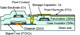
FIGURE 7 — Schematic cross-sectional view of the ZnO TFTs backplane for AMLCDs.
|
Advanced IPS technology for mobile applications
N. Aoki
S. Komura
T. Furuhashi
M. Adachi
O. Itou
T. Mi yazawa
M. Ohkura
Hitachi Displays, Ltd., Japan
Abstract — In-plane-switching LCD (IPS-LCD) technologies originally developed for LCD monitors and TV applications are applied to mobile applications. Advantages of the IPS mode over other optical modes for mobile applications are quantitatively clarified. The panel achieves stable color reproduction and chromaticity in the viewing-angle range for mobile displays. Superiority of the IPS mode over other optical modes is discussed also from the viewpoints of stability in chromaticity during the brightness change and the driving power consumption. A transflective IPS mode with good performance is accomplished by the use of a proper optical design. A new structure, IPS-Pro, which enables sunlight readability by increasing the transmittance, i.e., the brightness of the panel, without additional cost and power consumption in contrast to additional fabrication processes required to fabricate the transflective mode is realized. Furthermore, to improve the users' convenience, an automatic luminance control system and a controllable viewing-angle device are developed. The panels developed fulfill the market requirements of increasing the function and performance variations and will be the most appropriate ones to be applied to mobile appliances, such as cellular phones, digital still cameras, music players, GPS, mobile TV sets, etc.
The measured results are plotted on the CIE chart shown in Fig. 2. In these figures, the black triangle denotes the color gamut of Macbeth RGB when the display is observed from the normal direction. Additionally, the gray triangle denotes the color gamut of Macbeth RGB when the display is observed from an oblique direction corresponding to the worst direction in the viewing-angle range for mobile use. As can be understood from the figure, in the case of IPS mode, the color gamuts of the normal and oblique directions are almost identical. On the other hand, in the VA mode, they differ from each other although the oblique angle is only 22°. The CRS of the VA mode is only 45%, while the CRS of IPS is 88%.
|
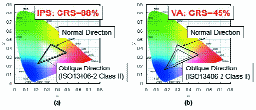
FIGURE 2 — Color gamut of Macbeth RGB (CG-MRGB). (a) IPS, (b) VA.
|
A novel hermetic-sealing material for FEDs
Kenji Ishizeki
Yuichi Kuroki
Mikio Ueki
Tsunehiko Sugawara
Akihiro Yamazaki
Yuichi Itou
Yasuhisa Fujii
Asahi Glass Co., Ltd., Japan
Abstract — An hermetic-sealing material for FEDs composed of thermosetting polyimide and glass fiber has been developed. The main backbone and end-capping material of polyimide were investigated to satisfy both high Tg and high flowability. A thermosetting function, 4-phenylethynylphthalic anhydride (PEPA), was used as the end-capping material. The fracture of a rigid and softening structure was optimized in the main polymer structure. The obtained polyimide demonstrated both a high Tg (265°C) and low viscosity (98 Pa-sec at a sealing temperature of 350°C). In order to improve the gas permeability and the mechanical and thermal characteristics of the sealing material, a mixture of various types of ceramic fillers and polyimide has been investigated, and glass fiber was adopted. When 30 wt.% of glass fiber was combined with the developed polyimide, the Ar permeability and coefficient of thermal expansion of the sealing material decreased to below one-half of the base polyimide. This material enables us to seal at a temperature of about 350°C in nitrogen atmosphere and shows superior performance suitable for glass-to-glass sealing.
As shown in Fig. 1, the heat stability of polyimide was superior to that of other organic materials and on a par with conventional inorganic solder glass used for the hermetic sealing of CRTs. Therefore, polyimide, which consists of dianhydride and diamine, has been adopted as the basic resin for the sealing material. Moreover, in order to attain high strength at the evacuation temperature, 250°C, and to adhere to the envelope, polyimide should have a high-glass-transition temperature
(Tg) of over 250°C and good flowability.
|
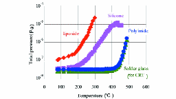
FIGURE 1 — Outgasing from various materials measured by thermal desorption spectroscopy (TDS).
|
A novel spacer-free panel structure and glass for FEDs
Tsunehiko Sugawara
Takahiro Murakami
Yuichi Kuroki
Mikio Ueki
Takeshi Naraki
Yasumasa Kato
Satoshi Kanasugi
Asashi Glass Co., Japan
Abstract — A new design for an FED envelope, composed of box-shaped front glass, sheet-like rear glass, and metal members, has been devised. This design structure is effective in reducing tensile stress induced by vacuum at the sealing points. Also, a new glass composition, a new physical tempering method, and a lead-free hermetic sealing material have been developed. As a result, a novel lightweight spacer-free panel structure for FEDs has been developed by integrating these new technologies. It will assist in maximizing the essential advantages of FEDs such as high image quality, high reliability, and low cost.
The 18-in. front glass was hermetically sealed to the rear glass at around 350°C by using our newly developed sealing material. After that, part of the rear glass was successively reinforced with a rear plate in the same manner as that of hermetical sealing. Figures 12(a) and 12(b) are photographs of the 18-in. front glass and the entire envelope, respectively. The bending at the center of the rear plate after evacuation was below 80 μm. The small bending for the long span will not affect the picture quality because it is possible to compensate, in advance, the relative displacement of the pixel position and emitter position.
|
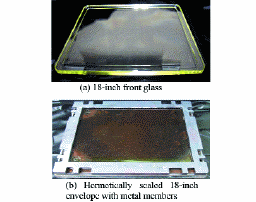
FIGURE 12 — Photograph of 18-in. envelope without spacers.
|
Making the best of legacy video on modern displays
M. Zhao
M. Bosma
G. de Haan
Philips Research, The Netherlands
Abstract — The recent revolution in display technology enables bright high-resolution displays, thereby removing one of the bottlenecks in video quality. How to profit from HD flat-panel displays when watching legacy SD-video material will be discussed. An overview of resolution up-conversion techniques will be presented, including an objective (MSE-scores) and a subjective assessment. Screenshots are also included to illustrate the quality of the algorithms.
The common procedure for mapping a video signal with the proper picture-rate and progressive scanning to a screen with a higher pixel count is scaling. This problem has been solved theoretically, and practical approximations of the theory exist that have been implemented and assessed in earlier overviews. These implementations, i.e., video-scaler integrated circuits (ICs), are available in all personal computers (PCs) and in most TVs. However, the scaling process does not add new frequencies. Our goal is to actually extend the spatial video spectrum, i.e., create frequency components that are not present in the SD signal, which could not even be represented on an SD display, but contribute to an increased picture quality when shown on an HDTV screen. Figure 1 illustrates the concept. To distinguish this technology from scaling, we shall call it Resolution Up-Conversion.
|
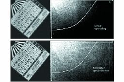
FIGURE 1 — Illustration showing the difference between spatial scaling (top) and resolution up-conversion (bottom) of an SD image to an HD grid. The bottom photograph is sharper, and its spectrum shows many new high-frequency components.
|
A psychophysical study of improvements in motion-image quality by using high frame rates
Y. Kuroki
T. Nishi
S. Kobayashi
H. Oyaizu
S. Yoshimura
Sony Corp., Japan
Abstract — The ideal frame rate for the highest motion-image quality with respect to blur and jerkiness is presented. In order to determine the requirements for avoiding these impairments, motion images from a high-speed camera and computer graphics were combined with a high-speed display to perform a psychophysical evaluation. The camera, operating at 1000 fps, and image processing were used to simulate various frame rates and shutter speeds, and a 480-Hz CRT display was used to present motion images simulating various frame rates and time characteristics of the display. Subjects were asked to evaluate the difference in quality between motion images at various frame rates. A frame rate of 480 fps was chosen to be an appropriate reference frame rate that, as a first estimation, enables coverage up to the human-dynamic-resolution (HDR) limit based on another experiment using real moving charts. The results show that a frame rate of 120 fps provides good improvement compared to that of 60 fps, and that the maximum improvement beyond which evaluation is saturated is found at about 240 fps for representative standard-resolution natural images.
When we consider the 24-fps frame rate used by cinema, 240 fps is an ideal frame rate because it provides the highest motion quality with straightforward image processing, such as synthesizing natural images and computer graphics, because 240 is a multiple of 24. Some sample images simulated for 60 and 240 fps are shown for computer graphics in Fig. 22 and for natural images in Fig. 23. In Fig. 22, each ball has a different motion vector and (a) and (b) are for the case of the pursuit of the 8 ball and (c) and (d) are for the case of the fixation view. In both cases, 240 fps provides higher quality compared to that at 60 fps.
|
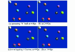
FIGURE 22 — Comparison between 60- and 240-fps computer-graphics images (simulated).
|
Moving-image simulation for high-quality LCD TVs
Ting-Wei Su
Jenn-Jia Su
Ting-Jui Chang
Po-Lun Chen
Kun-Yu Lin
C. T. Liu
AU Optronics Corp., Taiwan, R.O.C.
Abstract — A simulation system incorporating pixel response and eye-trace integration was developed to evaluate the moving-image performance of high-quality LCD TVs. A simple formula was derived for moving-edge simulation, which can be used to evaluate the visual effects of arbitrary response waveforms. A model of exponential decay with dynamic time constants is proposed for the LC response to perform moving-image simulation. The model was used to evaluate the visual effects of various motion-blur-reduction techniques. Six different motion-blur-reduction techniques were evaluated in terms of their visual effects. Among them, three basic techniques show certain defects, which are further analyzed by simulation. The other three advanced techniques show excellent performance, and, therefore, are recommended for use in high-quality LCD TVs.
The principle of eye-trace integration is illustrated in Fig. 1. If an image moves with a constant speed across a hold-type display with an ideal response time and the human visual system traces the edge smoothly, all optical responses of the pixels scanned by the human eye will be integrated. Although the human eye moves continuously, the image itself moves in an intermittent manner and changes its position only at the beginning of each frame (shifted v pixels toward the right after every frame time TF). Therefore, the moving image creates a blurred edge on the retina of the human eye, even if the LCD panel has an ideal response time. On the contrary, the moving image on an impulse-type display, e.g., a CRT, creates a clear edge because the image is only displayed at the beginning of each frame and no blurring effect is created during the "black" periods.
|
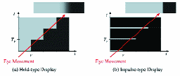
FIGURE 1 — The visual effect of eye-trace integration.
|
Evaluation of liquid-crystal-display motion blur with moving-picture response time and human perception
Jun Someya
Hiroaki Sugiura
Mitsubishi Electric Corp., Japan
Abstract — The moving-picture response time (MPRT) for measuring liquid-crystal-display (LCD) motion blur was studied by several organizations in 2001. To determine the LCD motion blur that humans perceive, subjective evaluation experiments using the method of adjustment was conducted to find a strong correlation between perceived motion blur and extended blurred edge time (EBET) of the MPRT measurements. MPRT thus clearly indicates the degree of which humans perceive motion blur.
MPRT is defined as quantifying the motion blur perceived by humans when viewing a moving image displayed on a liquid-crystal panel during smooth-pursuit eye tracking (SPET), i.e., when the eyes are smoothly pursuing a moving object. This definition enables us to measure MPRT using a typical CCD camera.
|
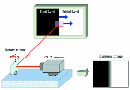
FIGURE 1 — A rotary mirror pursues and captures the edge of the image. |
The effect of FLCoS-display hold time on the perceived blur of moving imagery
George A. Geri
William D. Morgan
AFRL Visual Research Laboratories,U.S.A.
Abstract — The on- and off-times of LCDs have decreased significantly over the past few years. However, long hold times, while increasing light output, have limited the temporal resolution of these devices. We varied hold time and used a perceptual technique to assess the resulting change in blur of a moving test target presented on an FLCoS display. The technique requires observers to adjust the gap between two vertical lines that move across the display at various speeds. It was found that for a 13.4-msec hold time, the threshold gap width, and thus by implication the perceived blur, increased significantly from about 3 to 22 pixels as line speed was increased. For hold times of 8, 6, 4, and 2 msec, threshold gap width remained approximately constant at between about 2 and 5 pixels as line speed was increased. The results of the perceptual test used here suggest that reducing FLCoS hold time to 8 msec significantly improves the quality of moving imagery. Further, decreasing the hold time to2 msec results in perceptual blur that extends over as little as 6 arc-minutes.
The onset and offset times of more recently developed ferroelectric liquid-crystal–on–silicon (FLCoS) displays are significantly less than those of conventional LCDs (Underwood, 2000). Therefore, although FLCoS displays are typically designed to provide illumination throughout the entire 16.7-msec video frame, they are capable of presenting the necessary luminance changes in as little as 3–4 msec. It is generally accepted that a hold time in this range will significantly reduce motion blur without recourse to the more-complex techniques.
|
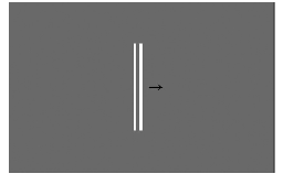
FIGURE 1 — The test stimulus used for the perceptual assessment of display temporal resolution. The arrow shows one direction of stimulus motion. |
Analysis, simulation, and evaluation of scrolling illumination as a method for reducing motion blur in LCOS projectors
Harry Streid
The Boeing Co., U.S.A.
Abstract — A high-fidelity simulation of motion blurring in an LCOS projector was developed by using the measured temporal response of the projector. The simulation was validated for continuous and scanning illumination by comparison with results of motion-blurmeasurements by using a pursuit camera. The simulation was then used to analyze and optimize duty cycle and phase parameters for scrolling illumination in the general case.
The simulation and training market is quite a bit more demanding than the LCD-TV market with regard to motion reproduction. Flight-simulator displays tend to be much larger in field of view than TV displays or computer monitors and in areas generally configured with multiple display devices. Specification and testing of resolution are usually done for static conditions only, since it is usual in the industry to assume the excellent motion reproduction of CRTs. As a result, any motion blurring which occurs if non-CRT displays are substituted may result in loss of training capability. The wide field of view (up to 360°) increases the tendency for observed flicker since the periphery of the human-visual system is more sensitive to this defect in the display.
|
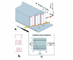
FIGURE 3 — Simulation of blurred edge profile for a perfect hold display device.
|