A preview of the papers appearing in the April 2007 issue of the Journal of the SID. To obtain access to these articles on-line, please go to www.sid.org
Edited by Aris Silzars
Composite silver electrode for double-sided-emitting stacked organic light-emitting diode
J. X. Sun
X. L. Zhu
Z. G. Meng
X. M. Yu
M. Wong
H. S. Kwok
The Hong Kong University ofScience and Technology
Abstract — A reflective composite silver electrode is proposed and characterized as the middle electrode of a stacked organic light-emitting diode (OLED) with double-sided light emission. The proposed electrode is composed of a thermally evaporated stack of LiF (1 nm)/Al (3 nm)/Ag (70 nm) layers. The LiF/Al and the plasma-treated Ag of the electrode function well as the respective cathode and anode of the bottom- and top-emitting stacked OLEDs, with both being of the non-inverted type. Power efficiencies of 10.3 and 12.1 lm/W at 100 cd/m2 have been measured for bottom- and top-emitting OLEDs, respectively, using dye doping. The stacked OLED having this bipolar middle electrode can be constructed as a two-terminal-only device, allowing for simpler driving schemes in double-side-emitting passive/active-matrix OLED displays.
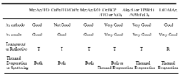
What is desired is a reflective bipolar middle electrode that is capable of serving as the respective cathode and anode of the non-inverted bottom- and top-emitting OLEDs in a stack. The construction of such an electrode, consisting of a thermally evaporated stack of lithium fluoride (LiF)/aluminum (Al)/silver (Ag) followed by a carbon tetrafluoride (CF4) plasma treatment is proposed here. Compared (Table 1) to the previously reported bipolar electrodes, the present proposed electrode is superior in both simpler construction and better performance. Additionally, only our proposed electrode is reflective instead of transparent so that it is suitable for fabricating double-sided-emitting OLEDs.
TABLE 1 — Comparison of the bipolar middle electrode with others in terms of performance and fabrication process.

In-band scalable video coding with integrated wavelet-based display driving
San Lam
Fabio Verdicchio
Herbert De Smet
Adrian Munteanu
Ghent University
Abstract — The increasing demand for multimedia over networks and the heterogeneous nature of today's networks and playback devices impose the stringent need for scalable video coding. In this context, in-band wavelet-based video-coding architectures offer full scalability in terms of quality, resolution, and frame-rate and provide compression performance competitive with that of state-of-the-art non-scalable technology. Despite these advances, video streaming over wireless networks to handheld terminals is lagging in popularity due to the high power consumption of the existing portable devices. As a possible approach to alleviate this problem, the integration of wavelet-based passive-matrix-display driving into the inverse discrete wavelet transform (IDWT) block of the in-band video decoding architecture was investigated. In a nutshell, the IDWT no longer needs to be performed by the decoder, being synthesized instead by the display itself. This integration reduces the number of calculations required to generate the driving waveforms for passive-matrix displays and inherently leads to reduced power consumption on portable terminals. Moreover, the wavelet transform and the considered video-codec architecture are both resolution-scalable. Hence, the resolution-scalability feature of the video codec, enabling resolution-scalable display driving, is another means to control the power consumption of the portable device.
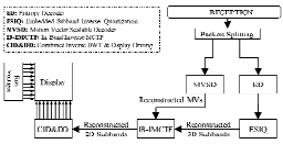
The rationale of using the in-band paradigm is that, in contrast to classical spatial-domain video-coding approaches, the decoding unit performs (spatial) inverse discrete wavelet transform (IDWT) as the last decoding stage, i.e., after motion-compensated temporal synthesis has been performed, just prior to displaying the decoded video frame. Therefore, by using the wavelet-based addressing technique, it is possible to combine spatial IDWT and display driving into a single block, thus deriving a simpler video decoder depicted in Fig. 2. This in turn results in decreased power consumption, which is a desirable feature for portable devices.

FIGURE 2 — Adapted decoder: the IDWT block is replaced by the combined wavelet inverse transform and display-driving architecture.
Noise-margin analysis of a-Si:H digital circuits
Zi Li
Sameer Venugopal
Rahul Shringarpure
David R. Allee
Lawrence T. Clark
Arizona State University
Abstract — The noise margin is one of the fundamental metrics in evaluating the viability and robustness of digital circuits. An analytical model of amorphous-silicon digital-circuit noise margin was developed, including the effects of circuit aging. The threshold voltage of a-Si:H transistors increases over time with electrical stress, degrading the performance and eventually leading to circuit wear-out. Since static and dynamic inverters are the basic digital-circuit design elements, they are the basis for this analysis. The analytical model is verified with experimental measurements. The lifetime of dynamic a-Si:H digital circuits is found to exceed the lifetime for static a-Si:H circuits by a factor of 2–3. Although the lifetimes are relatively short (~105 sec) and under continuous electrical stress, they are sufficient for low-duty-cycle applications.
The low-temperature a-Si:H process has been designed for flexible plastic (heat-stabilized poly-ethylene-napthalate) and flexible stainless steel. All process steps are below 180°C. The TFT is a bottom-gate inverted staggered design (Fig. 3). The a-Si:H channel is passivated to protect the back channel from contamination during subsequent process steps. Typical electron mobility extracted from the saturated TFT current is 0.5 cm2/V-sec. The ON/OFF ratio exceeds 106. Threshold voltages are around 4 V with a hysteresis of approximately 1 V.

FIGURE 3 — Inverted staggered bottom-gate a-Si:H TFT with channel passivation.
A novel spectrum-sequential display design with a wide color gamut and reduced color breakup
Erno H. A. Langendijk
Philips Research Laboratories
Abstract — The advantage of RGB color-sequential displays is that they have no color filters, but the disadvantage is that they need to run at high refresh rates (> >180 Hz) to prevent flicker and color breakup. An alternative color-sequential display, which can operate at relatively low refresh rates (~100 Hz) without disturbing color breakup or flicker, has been developed. The display has two color filters per pixel (cyan and magenta) on the LCD panel and the backlight can generate two types of spectra (blue-green and green-red), which results in a wide-gamut four-primary display, effectively. One part of the paper describes the color reproduction, including color-filter design, gamut mapping, and multi-primary conversion. The other part deals with the reduced perception of color breakup on the novel spectrum-sequential display compared to conventional color-sequential displays.
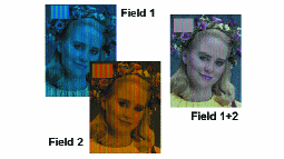
In order to illustrate the front-of-screen performance of the display, we simulated it in Fig. 6. The left and middle panels show the images of the first and second field, respectively. Note that the image of field 1 contains only cyan-blue colors and the image of field 2 only red and green colors, which correspond to the primaries of the display in the respective fields. The right image shows that the eye sees a full-color image with the correct colors when the images are played sequentially at a refresh rate of 120 Hz. The inset in the upper left corner is a zoomed image of part of a person's forehead. It clearly illustrates the different colors that are made in a single subpixel.

FIGURE 6 — Illustration of the two fields in the case of an actual image of a girls face and the resulting image as seen by the eye when presented at a refresh rate of 120 Hz. The left corner shows a zoomed image of the forehead. One can clearly see the striped pattern and the difference in the color of the pattern in each field and the resulting field.
Optical rewritable liquid-crystal-alignment technology
Alexander Muravsky
Anatoli Murauski
Xihua Li
Vladimir Chigrinov
Hoi-Sing Kwok
The Hong Kong University ofScience and Technology
Abstract — A new optical rewritable (ORW) liquid-crystal-alignment technology has been developed to create a display and to demonstrate its maturity and potential. ORW displays have no electrodes and use polarizers as substrates. The display requires no photolithography on plastic. Its simple construction secures durability and low cost for mass production. The on-screen information is optically changed in a writing unit that consists of an LCD mask and an exposure source that is based on LEDs, low power, and low cost in comparison with Hg lamps or lasers. A high contrast image can be easily written, viewed, and rewritten through a polarizer, while the multi-stable gray-level image requires zero power to maintain the image. Reconfigurable LC alignment using ORW technology best suits plastic-card displays as well as for LC photonics and various one-mask processes of patterned LC-alignment applications.
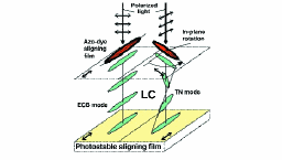
Switching and continuous gray scale are achieved by controling the aligning direction of the photoaligning azo-dye layer, which is insoluble in liquid crystal. A polarization controller system was successfully implemented to write, erase, and rewrite the image on an ORW LCD. It is based on a double LCD phase mask that can rotate the linear polarization direction of transmitted light at any angle from 0 to π. The construction of an LCD mask is as simple as that of a TN-LCD, and it can be both a passive and active matrix.

FIGURE 2 — The operational principle of an ORW LCD: Azo-dye aligning film rotates its aligning direction in-plane remaining perpendicular to the polarization of the writing light. The LC follows the top aligning direction switching between the ECD and TN modes.