A preview of the papers appearing in the March 2006 issue of the Journal of the SID. To obtain access to these articles on-line, please go to www.sid.org
Edited by Aris Silzars
Assembly technology for the manufacture of LCOS panels
D. Cuypers
H. De Smet
A. Van Calster
IMEC, TFCG
Abstract — The technological issues related to the fabrication of high-performance LCOS displays are described. The considered devices use the vertically aligned nematic liquid-crystal mode because of its superior performance characteristics. The issues addressed mostly stem from this choice and the ensuing need for inorganic alignment layers. In particular, the compatibility of the inorganic alignment layers with the sealant material are treated in detail.
The choice of the liquid-crystal mode is one of the key parameters that will determine the performance of the entire device. Of course, the benefits of a certain mode have to be outweighed to what is available in other modes. A choice for a certain liquid-crystal mode is always a compromise, tailored to the needs of the specific application. The main strength of the vertically aligned mode is its achievement in contrast ratio. The virtual absence of residual birefringence in the black, undriven state makes the contrast ratio for perpendicular light incidence almost only dependent on the quality of the polarizers. The only determining parameter here is the pre-tilt angle, i.e., the small deviation from perfect vertical alignment needed for reliable switching of the molecules.
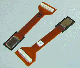
FIGURE 11 — Packaged WXGA LCOS devices.
Development of an 8-bit VGA LCOS microdisplay with FSC modes using a low-cost process
Yongping Dai
Yanyan Liu
Weidong Geng
Zhonglin Sun
Nankai University
Abstract — A VGA-resolution LCOS microdisplay operated in the field-sequential color (FSC) mode was fabricated using a low-cost process. An 8-bit digital data driver with digital-to-analog converters, which can realize a 256-level gray scale and gamma compensation, has been integrated into a color microdisplay. A top-to-bottom approach to the design of an FSC LCOS microdisplay is described. The design of the silicon-backplane circuits is outlined in detail. Finally, a prototype of this display and its imaging performance are discussed.
In order to implement LCOS chips at low cost, selected standard processes, including CMP to fabricate the backplane, and older-generation lines were used, whenever possible to incur lower production costs on fully depreciated and under utilized equipment. A very important aspect of the backplane design is the pixel-cell structure. The cell must store and sustain the accurate LC voltage levels needed to produce 256 gray scales. Since inexpensive semiconductor processes with one polysilicon and three metal layers were used to fabricate the LCOS chip, a MOS capacitor has to be used as a storage capacitor in each pixel cell. The pixel layout is shown in Fig. 6.
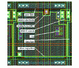
FIGURE 6 — The physical layout of the pixels.
Optimization of contrast for MTN45 LCOS panel
Yong-Jing Wang
Wavien, Inc.
Abstract — MTN45 LCOS was studied experimentally and by simulation. Optimized retardance and orientation of the compensation retarder were found by simulation and verified by experimental data for both wire-grid PBS and McNeil-type PBS systems. The parasitic reflectance from the counter-electrode (CE) glass and the retarder surface are two major effects that decrease the contrast of LCOS panels. Their effect was simulated by inserting several imaginary optical layers into the real system. Results also show that decreasing the retardance of the retarder, thus increasing the maximum driving voltage for the dark state, can increase contrast. By combining all the improvements, a contrast of 1500:1 in green and a contrast of 1000:1 in blue for MTN45 LCOS panels can be achieved.
Contrast ratio of HDTV has become one of the most crucial factors that affect the market share of a particular technology. DLP technology still produces the highest contrast among existing projection technologies. However, LCOS is catching up. The contrast improvement in the contrast of LCOS panels has attracted a lot of attention recently. Especially the mixed TN45 (MTN45) mode of LCOS is of great interest because it has a response time of about 0.1 msec. This fast response is critical in single-panel LCOS, including the scrolling-color light engine developed by Philips and color-wheel light engines by many other companies.
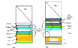
FIGURE 10 — Emulation of parasitic reflection by inserting imaginary layers. (a) Configuration of a real projector. (b) Emulation of a real projection image block by inserting imaginary layers.
Uniformity metrology in ultra-thin LCoS LCDs
Roland van Gelder
George Melnik
Miradia
Abstract — The synergy between measurement methodology and process development to monitor, control, and qualify the uniformity of the ultra-thin cell-gap single-panel liquid-crystal–on–silicon (LCoS) device will be described.
In order to meet the stringent device fast response time requirements needed in a color-sequential single-panel projector, a film-compensated 45° twisted-nematic normally white liquid-crystal mode has been selected with a 1-μm ultra-thin cell gap. In order to maintain a uniform thin cell gap, the integrated spacer technology has been developed. In general, this chosen LC mode has shown promising capability. However, discoloration observed at dark gray levels hampered satisfactory image quality. Several measurement methodologies which have been developed with the objective to identify major contributors to this discoloration will be described.
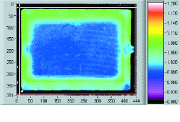
FIGURE 8 — Cell-gap uniformity map at 30°C.
Fast-response nematic liquid-crystal mixtures
Sebastian Gauza
Chien-Hui Wen
Benjamin Wu
Shin-Tson Wu
Anna Spadlo
Roman Dabrowski
University of Central Florida
Abstract — High birefringence and relatively low-viscosity isothiocyanate-based liquid-crystal compounds and mixtures were developed. A high figure-of-merit (FoM), which implies a fast response time of the described liquid crystals, was observed. Using the new UCF mixture in a 2-μm cell, a submillisecond response time was obtained. The UV stability dilemma is discussed as a common concern for high-birefringence LC materials.
In order to achieve a fast response time, low-rotational-viscosity (γ1) LC mixtures are preferred. Another straightforward approach is to use a thin cell gap filled with a high birefringence (Δn) and relatively low-viscosity LC mixture. Recently, many manufacturers reported display devices with cell gaps below 4 μm. Progress in the LCD manufacturing allows for introducing new high-birefringence LC mixtures which are favorable for achieving a faster response time. The most effective way to increase birefringence is to linearly elongate the π-electron conjugation length of the LC compounds.
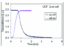
FIGURE 3 — Switching time measured for on-off-on sequence of the UCF mixture filled into a 2-μm homogeneous cell. Cell temperature was stabilized at 23°C.
A lifetime model for LCOS panels under intense illumination
Viktor Konovalov
Julia Fauchille
Sergei Yakovenko
MicroDisplay Corp.
Abstract — The mechanisms of photochemical reactions occurring during the operation of LCOS panels under intense illumination are analyzed. Regardless of the liquid-crystal-mixture formulation, light may generate radicals in the liquid crystal and the polyimide alignment layer. The interaction of these radicals modifies the PI surface and causes alignment degradation. Using kinetic equations for these processes, a lifetime model for the LCOS panels is developed. This new model of lifetime dependence versus light intensity is found to be in agreement with experimental data. This model verifies the TN LCOS panel lifetime to be in excess of 50,000 hours for RPTV applications.
LCOS panels are used in various types of light engines. UHP lamps are commonly used in projection applications as the light source with the UV part of the spectrum cut off by filters. To achieve sufficient brightness on the projection screen, i.e., 400–500 nits, the luminance at the panel inside a single-panel engine varies in the range of 5–2 Mlux (depending on the light-engine architecture). The intensity on the panel also depends on the panel size. In three- and two-panel engines, an equivalent amount of blue light is incident on only one of the panels, causing similar light damage compared to the entire visible spectrum.
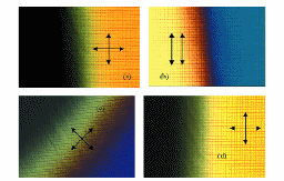
FIGURE 5 — "Damaged" (left side of each picture) and "non-damaged" (right side) parts of panel under the microscope in polarized light. The transient area between these two is caused by a rapid decrease of the light intensity outside of the light pattern and allows us to trace alignment variation with light dose increase. Directions of polarizer and analyzer are shown in each case by the arrows.
Second wind of the oblique deposition method of liquid-crystal alignment: Ion-beam sputtering technique
A. Khakhlou
A. Murauski
O. Yaroshchuk
E. Telesh
R. Kravchuk
IZOVAC, Ltd.
Abstract — Liquid-crystal (LC) alignment on SiOx films produced by ion-beam sputtering deposition was comprehensively studied. The conditions for planar, tilted planar, homeotropic, and tilted homeotropic LC alignment of high uniformity were determined. The alignment photostability and aging issue are discussed. An original sputtering system based on the anode-layer source excelling in high reliability and quality of sputtered coatings were used. Because this system can be easily scaled up, the alignment treatment of the large-area alignment substrates, including those used in modern LCD manufacturing, can be realized. The advantages of the sputtering LC alignment technique, in comparison with its vapor-deposition predecessor, are described.
The scheme of the sputtering source and deposition geometries are presented in Fig. 1. We used the sputtering device developed by IZOVAC, Ltd. It is based on the anode-layer ion source with the racetrack shape of the discharge area. It generates two sheet-like fluxes of Ar+ ions focused on the surface of a lengthy target with the dimensions of 60 ´ 500 mm2. The incidence angle of ions onto the target, determined from the target's normal, is about 60°, which allows the attainment of the maximal efficiency of sputtering at the same power consumption. The ion-source aperture limits the flux of sputtered material providing its partial collimation.
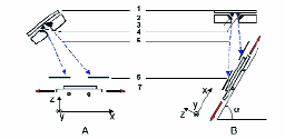
FIGURE 1 — Scheme of sputtering source and sputtering-deposition geometries. 1–3 — parts of sputtering source (1 – target; 2 – cathodes and magnet system; 3 – anode); 4 – ion beam; 5 – flow of sputtered particles; 6 – diaphragm; 7 – moving platform with substrates.
Contrast optimization for MacNeille-PBS-based LCOS projection systems
Jianmin Chen
Michael G. Robinson
Gary D. Sharp
ColorLink, Inc.
Abstract — Contrast limits are investigated for MacNeille-PBS-based LCOS projection systems that use retarder stack filters (RSFs). The two contributing factors are considered separately; namely, the color-management system and the panel port. To enhance performance of the former, skew-ray-compensated RSFs are introduced. For the latter, a general three-step methodology is presented to optimize contrast by compensating the LCOS panel. It is shown that the orientation of the LCOS panel and compensator, relative to the MacNeille PBS, is critical. The significant impact of AR-coating performance on system contrast is also revealed. Methods to enhance ANSI contrast are proposed. A high-contrast architecture will be presented by way of example.
The slow introduction of LCOS into the video projection market is due, in part, to difficulties in achieving high system contrast, which is considered the most important performance specification of a projection system, as it ultimately influences the number of true-gray-scale levels and the color fidelity. The difficulty stems from its unique reflective operation mode, which requires precise control of polarization and is compounded by the double pass through components adjacent to the panels. This paper addresses the contrast issues by separating the color-management system contribution from that of the panel.
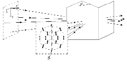
FIGURE 2 — Illustration of polarization axes rotation of skew rays propagating through a MacNeille PBS. The degree of polarization rotation of s-polarization is a function of incidence angle.
Wire-grid polarizers in modern LCOS light-engine configurations
Michael Pate
Jim Meyer
Joe Shiefman
Doug Hansen
Optical Short Course International
Abstract — Wire-grid polarizers that have a very high transmission, reflection, polarized-light optical performance, and opto-mechanical packaging advantages compared to the older polarization technologies have been developed. The wire-grid polarizer operation principles and performance data are reviewed. The power of using finite-difference time-domain (FDTD) modeling techniques to understand the interaction of the electromagnetic waves with the wires and improve the optical performance of the wire-grid polarizers and ultimately the light-engine optical performance is shown. The ability to ray trace through a complete digital projector light engine from light source to the screen, including the wire-grid polarizers, will be discussed. The main focus is to present the modern LCOS light-engine architectures that use the wire-grid polarizers. One-, two-, and three-panel LCOS light engines are covered.
Because the size of the metal wires is sub-wavelength, we cannot use typical lens design and illumination design software that works in the scalar diffraction regime to model light interaction with these structures. We must use different techniques to understand the interaction of the electro-magnetic waves with these small sub-wavelength structures. Both the finite-difference time domain (FDTD) and Rigorous Coupled Wave approaches have proved effective in modeling the MicroWire™ structure. In this paper, the FDTD modeling is discussed.
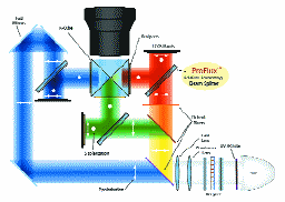
FIGURE 14 — Three-panel LCOS light engine architecture with flys-eye illumination system and ProFlux™ wire-grid polarizing beam splitters from MOXTEK®.
Compensation of birefringence in lead-free polarizing beam splitters for LCOS projectors
David J. W. Aastuen
Charles L. Bruzzone
3M Optical Systems Div.
Abstract — Most optical designs for delivering light to LCOS imagers and then from the imagers to the projection lens use polarizing-beam-splitter (PBS) technology. Most of the PBSs used in commercial LCOS projectors contain glass with a significant amount of lead (Pb). Such glasses have inherently low stress birefringence, and therefore maintain the polarization state of light passing through them. However, Pb-bearing glass is expensive and difficult to process and contains hazardous material with special disposal requirements and is therefore not desirable in consumer-electronic products. On the other hand, Pb-free wire-grid plate PBSs require a longer back focal length than would be optimal. Data and modeling results show that uniform high-contrast dark states may be obtained from lead-free-glass Cartesian PBS prisms when a quarter-wave compensator is used between the imager and the PBS.
It has long been known that it is necessary to compensate for a number of effects to obtain high contrast for PBS-based LCOS imaging systems. For example, if a MacNeille PBS is used, it is necessary to compensate for the geometrical effects arising from rotation of the reflection plane on reflection from the imager. It is also widely understood that, in addition to these effects, imager compensation is required to achieve high contrast (over 1000:1), especially with the popular vertically aligned nematic (VAN) mode imagers.
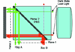
FIGURE 10 — Depiction of ray paths through PBS. Ray B has its polarization mixed more than Ray A because it travels through more of the PBS after reflecting off the PBS surface.
Contrast behavior of a field lens with a wire-grid PBS
Khalid Shahzad
Jeffery A. Shimizu
Philips Research USA
Abstract — In an LCOS projection system, a wire-grid PBS may be used to improve contrast, and a field lens may be employed to simplify the projection lens. However, the combination of the two leads to a reduced contrast, which decreases with increasing field angle in one direction. In a representative arrangement, measured contrast with a mirror varied from over 10,000 in the center to 450 at the left and right edges. Contrast loss can be improved with a weaker field lens. The problem arises due to a phase delay between polarization states introduced by the wire grid. Polarization measurements show a +53-nm phase delay with an axis parallel to the wire-grid surface normal. Various compensation schemes are proposed in order to reduce the aforementioned loss of contrast.
A field lens, used between the PBS and the LCOS panel, helps reduce the size of the imaging optics assembly, which results in significant cost savings. It was found, however, that this configuration leads to a serious contrast problem. The field lens changes the geometry of the ray paths and the wire-grid PBS changes the phase of the incoming linear polarized beam. The precise origin of this polarization phase change by the wire grid is not known. As a result, there is a significant loss of contrast in the skew direction, out of the primary plane of incidence.
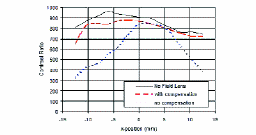
FIGURE 8 — Measured image contrast with an LCOS panel: panel without a field lens, panel with a field lens including phase compensation via panel drive voltage, and with field lens with no voltage compensation.
Three-panel LCOS projection systems
Michael G. Robinson
Jianmin Chen
Gary D. Sharp
ColorLink, Inc.
Abstract — Three-panel liquid-crystal–on–silicon (LCOS) projection systems are presented with an emphasis on the commercially successful shared retarder-stack-filter (RSF) polarizing-beam-splitter (PBS) architectures. The design and operation of the specific CQ90 projection core is presented in detail, and its contrast and transmission derived. Alternative three-PBS/X-cube LCOS architectures are briefly introduced and their performance is compared to that of the CQ90.
The key architectural building block of RSF-based three-panel LCOS panel systems is a single shared PBS (sPBS) used to split and then combine light from two separate panels. Polarized light is input into one of the ports of the sPBS through an RSF. The sPBS then splits the light according to color-coded polarization and illuminates panels situated at the second and third PBS ports. The reflected light, altered in polarization by the panels' LC, then recombines and exits the fourth port. To avoid p-polarized crosstalk between channels, another RSF is placed at the output to allow clean up of this unwanted polarized component by a neutral analyzer.
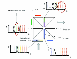
FIGURE 8 — CQ90 architecture showing filter spectral designs and skew-ray correction.
An LCOS-based digital-cinema projector
Andrew F. Kurtz
Barry D. Silverstein
Joshua M. Cobb
Gary E. Nothhard
Xiang-Dong Mi
James T. Stoops
Franklin D. Ehrne
David J. Nelson
Eastman Kodak Co.
Abstract — A digital cinema projector that utilizes three QXGALCDs and provides 12,000 lumens, 2000:1 contrast, and 3-Mpixel resolution was developed. This system, which was described in a prior paper, has a novel optical configuration based on the use of intermediate imaging optics and wire-grid polarizers and is described in greater detail in this paper. The polarization optics, including the polarization compensators, contribute to a system that provides high contrast at a low f/#, with a wide color gamut and minimal color shading at high power.
This system represents the first demonstration that reflective LCOS microdisplays are a viable technology for use in digital-cinema projection systems because the system provides the brightness, contrast, and resolution necessary to satisfy both consumers and the motion-picture industry. In particular, it has been demonstrated that R-LCOS panels and the associated polarization optics can function in the harsh environment of a high-lumen projection system. Although this design has an obvious complexity, it has numerous advantages and is robust and easy to assemble and use.
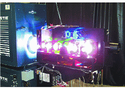
FIGURE 12 — Projector structure.
Suppression of color breakup in color-sequential multi-primary projection displays
Erno H. A. Langendijk
Stefan Swinkels
Dan Eliav
Moshe Ben-Chorin
Philips Research Laboratories
Abstract — Field-sequential projection displays exhibit a phenomenon of color breakup (Rainbow effect). This is considered to be a disturbing artifact with negative marketing impact. The results of a psychophysical experiment comparing the visibility of the phenomenon in RGB and multi-primary displays is described. Surprisingly, it is found that color breakup in color-sequential projection displays with five primaries is equally (for 75 Hz) or less (for 105 Hz) visible than in similar displays with three primaries (at 180 Hz), despite the lower refresh rates.
In multi-primary displays, more than three color fields are used to represent the full-color image. Therefore, at first glance, higher data rates and even faster light-valve response times may be required in order to build color-sequential multi-primary displays. A question arises whether a multi-primary display, which due to response time limitation, will operate at a relatively low frame rate compared to an RGB display, would be acceptable.
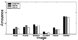
FIGURE 4 — Annoyance of color breakup for each of the six images for a three-primary display at 180 Hz and five-primary displays at 105 Hz and 75–85 Hz. Annoyance was directly related to the question if consumers would buy a TV set with the amount of color breakup shown (1 = yes, 2 = probably yes, 3 = probably no, 4 = no).