The Path toward Flexible OLED Displays
By using a metal-foil substrate instead of glass, flexible OLED displays can be significantly thinner, lighter in weight, and more rugged than existing LCDs. This article describes the fabrication and performance of a full-color 100-ppi QVGA flexible PHOLED and discusses the current challenges and future prospects of this revolutionary display technology.
by Anna B. Chwang, Mike Hack, and Julie J. Brown
MOST major active-matrix liquid-crystal-display (AMLCD) manufacturers are installing or have announced plans to establish manufacturing lines for active-matrix organic-light-emitting-diode (AMOLED) display products. OLED technology is ideal for flat-panel-display applications where low power consumption, video image quality, thinness, and light weight are desired. An additional, unique attribute of OLEDs is their potential application in flexible or conformable products due to the demonstrated flexibility of OLED technology.1 In the past several years, there has been significant progress in realizing flexible OLEDs (FOLEDs).
Our goal is to develop FOLED displays that will repeatedly roll out to large areas, e.g., a large-area display that can be pulled out from a pen-like case or housing. These high-information-content OLED displays require the integration of an OLED frontplane with a flexible thin-film-transistor (TFT) backplane, so the development of such AMFOLED displays involve a more-stringent set of technical requirements to ensure that the entire display, including the TFT backplane, OLED frontplane, and encapsulation, can withstand the stresses of multiple flex usage.
Although most FOLED work to date has been focused on thin plastic films, today there is an incompatibility between the temperatures required for the fabrication of a TFT backplane capable of driving an OLED display (>300°C) and the maximum allowed process temperature of conventional plastic substrates. In addition, it is important to ensure that displays for mobile applications do not become too hot to handle (>50°C), thus low-power-consumption is required.
Our approach to flexible AMOLEDs for rollable applications includes the selection of metal foil as a high-working-temperature substrate that is compatible with a low-temperature polysilicon (LTPS) TFT process. We initially chose LTPS TFT technology because of its higher performance over that of amorphous-silicon (a-Si) TFTs because of the possible reduction in the number of external connections via the integration of shift registers and/or multiplexing circuits that make LTPS more suitable for rollable displays. Low power consumption is achieved through the use of phosphorescent OLED (PHOLED™) technology.
Our power-efficient flexible AMOLED displays integrate three key enabling technologies: high-efficiency top-emission PHOLEDs, LTPS TFT backplanes, and flexible thin-film encapsulation. High-efficiency PHOLEDs2 enable low power consumption and significantly reduce the display operating temperature – in these systems, both singlet and triplet excitons are harvested as phosphorescent radiation, leading to efficiencies up tofour times that of their fluorescent counterparts.
The LTPS TFT backplane provides the desired performance for driving AMOLEDs, and we have selected a multilayered, thin-film encapsulation approach to protect the OLEDs from moisture and oxygen contamination as well as to allow for flexibility of the encapsulated display.
Results
Our results include the performance of single test pixels as well as QVGA displays on metal foil. Both incorporate top-emitting PHOLED (T-PHOLED) technology.
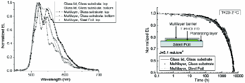
Single Test Pixels. As a first step toward integrating our PHOLEDs with steel-foil backplanes, we fabricated 5-mm2 PHOLED test pixels on planarized steel foil. The steel foil was planarized with a 3-μm-thick insulating layer. The T-PHOLED device had a green phosphorescent emitter in the emissive layer and used a thin-metal/transparent-conductive-oxide (TCO) cathode. Figure 1 shows the normalized electroluminescent (EL) spectrum and the lifetime of a representative T-PHOLED test pixel on steel foil (multilay-
ered Al2O3/ polyacrylate encapsulation provided by Vitex Systems3). Included for comparison are data for two T-PHOLEDs on a transparent glass substrate encapsulated with either a glass lid or a multilayered thin film. The additional features in the EL spectrum of the thin-film encapsulated pixels are caused by the refractive-index mismatch of the oxide and polymer layers in the encapsulation stack, which result in interference fringes that are superimposed onto the spectrum. The features do not have a negative impact on the color coordinates of the EL emission.
Anna B. Chwang, Mike Hack, and Julie J. Brown are with Universal Display Corp., 375 Phillips Blvd., Ewing, NJ 08618; telephone 609/671 0980, fax 609/671 0995, e-mail: mikehack@universaldisplay.com.
The lifetime data of the devices driven by a constant direct current drive with a current density of 3.1 mA/cm2 were measured. The degradation of the devices is comparable, and time to half-luminance is greater than 5000 hours. These results are encouraging and demonstrate the viability of a multilayered packaging approach to T-PHOLEDs on flexible metal foil.4
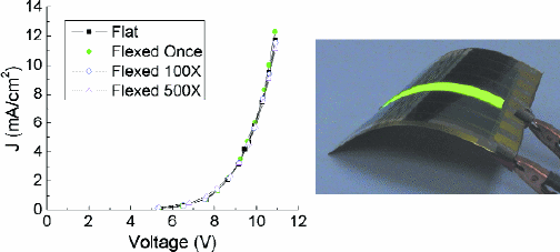
Flexibility Testing. To demonstrate the flexibility of our PHOLEDs fabricated on a 100-μm-thick metal-foil substrate, Fig. 2 shows the results of the current–voltage (I–V) characteristics of a T-PHOLED icon encap-sulated by Vitex Systems, after being repetitively flexed around a 3.5-cm radius of curvature. The results show no appreciable change in the I–V characteristics after 500 flexes.

Fig. 1: Normalized EL spectra (left) and lifetime (right) for a glass-lid-encapsulated T-PHOLED on glass, multilayered thin-film-encapsulated T-PHOLED on glass, and multilayered thin-film-encapsulated T-PHOLED on steel foil.

Fig. 2: Current–voltage characteristics of a top-emission encapsulated PHOLED icon after repetitive flexing around a 3.5-cm radius of curvature. The photograph on the right shows the PHOLED icon.
QVGA AMOLED Displays
Figure 3 shows the results of our early demonstration of QVGA AMOLED displays on metal foil incorporating an LTPS backplane, top-emission OLEDs, and multilayer thin-film encapsulation technologies. The LTPS backplanes are fabricated by our partners at the Palo Alto Research Center (PARC) on 100-μm-thick planarized steel foil and comprise a 2-TFT striped pixel design with a 100-ppi resolution. The process is based on PARC's excimer-laser-annealed poly-Si process on glass substrate.5 The top-emission OLEDs are deposited by a high-resolution shadow mask using conventional vacuum thermal evaporation. The red and green OLED components are phosphorescent; we chose to use a fluorescent blue for this early demonstration and will replace it with phosphorescent blue when improved lifetime performance of the blue PHOLED is achieved. The multilayered Al2O3/polyacrylate encapsulation was provided by Vitex Systems, and L3 Display Systems developed the appropriate drive electronics.
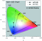
The QVGA display supports full-motion video and has 64 gray-scale levels. The RGB and white color coordinates measured from the display are shown on the 1931 CIE chromaticity chart (Fig. 4). It should be noted that an improved white closer to CIE coordinates (0.33,0.33) can be achieved with the chosen RGB system upon further tuning of the drive electronics.
Summary and Outlook
We have demonstrated both single test pixels and QVGA AMOLED displays with 100-ppi resolution on planarized steel foil. Lifetime and flexibility testing data were also presented for the test pixels with multilayered encapsulation. There are still more improvements that need to be made before truly flexible, roll-out displays are realized. However, early results are encouraging and demonstrate the viability of our approach to fabricating flexible displays on metal foil. We believe we have outlined a technology path to the realization of a new range of flexible and conformable display products that will, in turn, enable flat-panel displays to be seen in a new light and in new form factors, not restricted to rigid-glass-based substrates.
Acknowledgments
We gratefully acknowledge our partners at PARC (Bob Street, Jackson Ho, and Jeng-Ping Lu), L3 (Dave Huffman, Keith Tognoni, and Bob Andersen), and Vitex Systems (Teresa Ramos, Lorenza Moro, and Nicole Rutherford). We also thank the Air Force Research Laboratory (Darrel Hopper), the Army Research Laboratory (David Morton and Eric Forsythe), and the Communications-Electronics Research, Development and Engineering Center (Raymond Schulze) for financial support of this work.
References
1G. Gu, P. E. Burrows, S. Venkatesh, S. R. Forrest, and M. E. Thompson, "Vacuum-deposited nonpolymeric flexible organic light-emitting devices," Opt. Lett. 22, 172-174 (1997).
2M. A. Baldo, D. F. O'Brien, Y. You, A. Shoustikov, S. Sibley, M. E. Thompson, and S. R. Forrest, "Highly efficient phosphorescent emission from organic electroluminescent devices," Nature 395, 151-154 (1998).
3L. Moro, N. M. Rutherford, M. Rosenblum, X. Chu, R. J. Visser, M. Gross, G. Graff, W. D. Bennett, J. Nagai, and K. Furuno, "Barix coating of OLED bottom and top emission displays," FPD International, Yokohama, Japan (October 20-22, 2004).
4We note that the device structure used in this study is not optimized for lifetime. Further optimizations to the structure should enhance the lifetime of the devices.
5R. T. Fulks, J. B. Boyce, J. Ho, G. A. Davis, and V. Aebi, Mater. Res. Soc. Symp. Proc. 557, 623 (1999). •

Fig. 3: Full-color image of a QVGA (320 x 3 x 240) AMOLED with a 100-ppi resolution on 100-μm-thick metal foil.

Fig. 4: Measured color coordinates for red, green, blue, and white on a QVGA AMOLED display on steel foil.