A preview of the papers appearing in the June 2005 issue of the Journal of the SID, available on-line at www.SID.org.
Edited by Aris Silzars
A4-sized flexible ferroelectric liquid-crystal displays with micro color filters
Hiroto Sato
Hideo Fujikake
Takeshi Murashige
Hiroshi Kikuchi
Taiichiro Kurita
Fumio Sato
Japan Broadcasting Co., Japan
Abstract — An A4-paper-sized flexible ferroelectric liquid-crystal (FLC) color displays fabricated by using a new plastic-substrate-based process which was developed for large-sized devices is demonstrated. Finely patterned color filters and ITO electrodes were formed on a plastic substrate by a transfer method to avoid surface roughness and thermal distortion of the substrate, which induce disordering of the FLC molecular alignment. The thickness of an FLC/monomer solution sandwiched by two plastic-film substrates was well controlled over a large area by using flexographic printing and lamination techniques. Molecular-aligned polymer walls and fibers were formed in the FLC by a two-step photopolymerization-induced phase-separation method using UV-light irradiation. A fabricated A4-sized flexible-sheet display for color-segment driving was able to exhibit color images even in the bent state.
Ferroelectric liquid-crystal (FLC) devices using thin plastic-film substrates are attractive for flexible displays with high-quality moving images based on fast response. Although FLC devices generally have disadvantages such as poor mechanical stability due to smectic layer structure, the methods to obtain the mechanical stability of flexible FLC devices have been proposed. A continuous gray-scale capability, which is another important issue for conventional bistable FLC devices, can also be obtained in FLC devices that use the V-shaped switching mode or half-V-shaped switching mode.
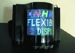
FIGURE 10 —Bent-state operation of a fabricated A4-sized flexible color FLC display.
Reflective cholesteric displays: From rigid to flexible
Asad Khan, Irina Shiyanovskaya,
Tod Schneider, Nick Miller,
Todd Ernst, Duane Marhefka,
Forrest Nicholson, Seth Green,
Greg Magyar, Oleg Pishnyak,
J. William Doane
Kent Displays, Inc., U.S.A.
Abstract — Bistable reflective cholesteric liquid-crystal displays are low-power displays that are suitable for a variety of applications ranging from signage to high-resolution electronic books. Recent advancements have included higher brightness, full color, black and white from a single layer, and lighting solutions. Cholesteric displays also lend themselves to simple integration into flexible materials since they may be coated and printed. We have developed reflective cholesteric displays on thin flexible plastic substrates, as well as other unconventional substrates such as paper and drapable fabrics. This paper serves as a review of recent advances in the cholesteric-display technology at Kent Displays.
The ChLCD technology is one of the most compatible technologies with existing STN manufacturing capability, including drive electronics, basic materials, and process and manufacturing tolerance. Many existing passive-matrix-LCD makers are interested in this technology because of these features. However, newer applications also demand newer display features, such as faster update speed, lighting solutions, and higher brightness and contrast. These requirements will eventually translate into new display materials, new display drive methods, and new display processes and configurations.
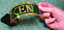
FIGURE 8 — Photograph of a flexible cholesteric display made using the polymerization-induced phase separation (PIPS) approach with two thin ITO-coated polycarbonate substrates.
Technologies toward flexible liquid-crystal displays
Shie-Chang Jeng, Ku-Hsien Chang,
Jau-Min Ding, Lung-Pin Hsin,
Chun-Yuan Lin, Yan-Rung Lin,
Kang-Hung Liu, Chih-Chiang Lu,
Yi-An Sha, Hsing-Lung Wang,
Chi-Chang Liao
ERSO/ITRI, Korea
Abstract — Several leading technologies for flexible liquid-crystal displays have been developed recently at ERSO. The roll-to-roll compatible techniques, polymer-added liquid crystal, have been applied on a film-like substrate. A flexible black-and-white cholesteric liquid-crystal display was also implemented by photo-induced phase separation. Color filters placed on a plastic substrate by a low-temperature manufacturing process were successfully fabricated. A novel design of a wide-viewing-angle color plastic LCD was also proposed.
The ultimate goal for a high-quality plastic LCD is to reach the same specifications as a high-quality glass LCD. Therefore, an LCD with wide viewing angle is also required. This requirement is more crucial for plastic LCDs used in a bending condition. We have proposed a novel design compatible with a next-generation roll-to-roll manufacturing process as shown in Fig. 10. The matrix-type micro-cell structures on the upper and lower plastic substrates are cross laminated. They serve as cell-gap controllers, the protrusion needed to produce the multi-domain required by wide viewing angles and the bank structure of the ink-jet color resist.
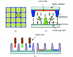
FIGURE 10 — The design of a color LCD with wide viewing angle. (a) Top view, (b) side view, and (c) ink-jet printing of the color filters.
Flexible-OLED-display development: Strategy and status
Anna B. Chwang
Michael Hack
Julie J. Brown
Universal Display Corp., U.S.A.
Abstract — In this paper, the current status of flexible OLED (FOLED®) display development will be reviewed, including previous results for passive-matrix displays on plastic and current progress on active-matrix displays on steel foil. The displays incorporate high-efficiency small-molecule phosphorescence OLED (PHOLED™) technology. The ultimate goal is to develop high-information-content, high-performance, long-lived, and large-area FOLED displays that can be pulled or rolled out from a smaller pen-like housing. The strategy for achieving this goal will be presented.
Unlike most plastics, metal foil substrates can withstand a large thermal load and do not require a moisture and oxygen permeation barrier. The metal-foil substrate itself can act as a diffusion barrier to moisture and oxygen. Active-matrix backplanes with conventional a-Si and LTPS TFT technologies require temperatures near 300 and 450°C, respectively. Metal-foil substrates can accommodate the thermal load; however, the maximum process temperature will be limited by the dielectric/planarization layer placed on the foil surface.
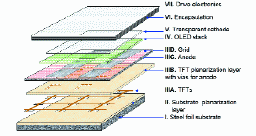
FIGURE 3 — Schematic diagram of an encapsulated AMOLED display on planarized steel foil.
Passive multiplexing of printed electroluminescent displays
Duncan Johnston
Chris Barnardo
Chris Fryer
Pelikon, Ltd., U.K.
Abstract — A method is required for creating a graphics display, or pixel array, from printed electroluminescent (PEL) display technology and driving it efficiently and cost effectively. The display is made up of a matrix of capacitive light-emitting display elements which are to be driven by a passive multiplexing method. A four-level drive system is required in order to produce the best possible contrast ratio on the display. A four-level drive system is costly to implement at the high voltages at which PEL displays operate, but a system is presented here which is able to make a significant reduction in the amount of electronics required to control the display. By selectively switching the output from a fly-back power supply to different parts of the matrix display, the optimum voltages can be obtained across all segments from a single high-voltage power supply. This provides potential for using passive-matrix PEL displays in a wide variety of applications, as well as having possible applications for other display technologies such as PDLCs (see demonstration in Fig. 1).
The solution to the challenge of devising an efficient and cost-effective passive-multiplexing system for PEL displays described here enables a single high-voltage supply to be used to produce the three levels required for optimum contrast ratio. The system presented here uses a single fly-back power supply to produce the high voltage required to drive the display. This voltage will vary depending on application, but will most normally be in the range 3–6 V. A pulse width modulator, normally a programmable device integrated within a microcontroller, provides a square wave signal to the gate of the FET, where the frequency and duty cycle of the square wave is controlled from the microcontroller. When the FET is turned on, current flows through the inductor (L), the current increasing linearly with time. When the FET is turned off, the current instead flows through the diode (D) and into the smoothing capacitor (CS) and whatever part of a display may be attached to Vout.
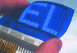
FIGURE 1 — A prototype passive-multiplexed printed electroluminescent display.
Characterization of flexible reflective liquid-crystal cells
S. Valyukh
J. Osterman
I. Valyukh
K. Skarp
Dalarna University, Sweden
Abstract — Peculiarities in testing flexible reflective liquid-crystal (LC) cells are considered. Several new methods for measuring optical retardation of filled reflective LC cells on plastic substrates are proposed. Cases when the plastic is anisotropic and the LC cell consists of either one or two internal polarizers are studied. The majority of proposed methods can be applied for transmissive LC cells as well as for measuring twist angle.
The following three cases are considered: (1) the plastic substrates are anisotropic; (2) a two-polarizer LC cell that includes only a back internal polarizer; and (3) a completed LCD. From the results, we can conclude that some proposed methods (parallel/perpendicular polarization, using a compensator, null spectroscopy) have reasonably high accuracy enabling us to measure the retardation in situ. The methods can be extended for determining the twist angle of LC cells.
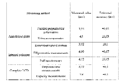
TABLE 2 — Results of the measurements for transparent LC cells on glass substrates adapted for each measuring method.
Avoiding on-screen metamerism in N-primary displays
Michael H. Brill
James Larimer
Datacolor/Color Vision, U.S.A.
Abstract — The present paper describes a method for using more than three primaries in an additive-primary display. The method ensures that each tristimulus specification can be produced in no more than one way, even if a non-singular filter (i.e., one that does not reduce the dimensionality of color-matching space) is interposed between the screen and the viewer.Starting with N primaries, the method uses only three at a time, but these may be composites –fixed linear combinations of the original N. As further insurance against on-screen meta-merism, a criterion on the primary spectra, based on the Binet-Cauchy theorem, ensures thata triad of primaries keeps its right/left-handed chromaticity ordering when a filter is interposed.
Flat-panel direct-view display technology relies on the eye's spatial blur to mix discrete primary color channels. Single-chip projection displays, e.g., display devices that use a single spatial light modulation channel, modulate light in several ways that include liquid-crystal light valves, micro-mirrors, and diffraction. Here the mixing of the primaries is enabled by the eye's slow temporal response or persistence. Such a display device always uses a broad-spectrum arc lamp as the light source. Solid-state light sources that are more efficient in converting electrons into photons in the visible spectrum are being developed for backlights and projector light sources. These future light sources are capable of temporal modulation that can be phased with spatially distributed amplitude modulation to reconstruct imagery. This paper addresses the problem of metamerism on current display devices and on future devices that will employ these new light sources.
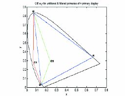
FIGURE 1 —Chromaticity space of a four-primary display, showing the migration of the C primary from C1 to C2 when a filter is introduced.
Motion adaptive CODEC Feedforward Driving for LCD overdrive
Jun Someya
Noritaka Okuda
Mitsubishi Electric Corp., Japan
Abstract — The authors have been developing a Feedforward Driving scheme as an overdrive technique to improve LCD response time. Focusing on the reduction of frame memory in overdrive in particular, they are now studying a memory-reduction method by applying an image-compression technique. An LSI has already been developed that incorporates a Compression Feedforward Driving unit, which successfully reduced image data to 1/3 by means of the image-compression technique. This paper reports a study of Motion Adaptive CODEC Feedforward Driving in which a motion adaptation process is added to the CODEC section of the Compression Feedforward Driving unit. This motion adaptation process reduces the amount of errors in overdrive that are caused by memory reduction by using a circuit of the same scale as that for Compression Feedforward Driving.
In this study, the authors considered the macFFD system in which a motion adaptation process is added to the CODEC section of a cFFD, and divided the subject into HDTV and SDTV categories. With the macFFD motion adaptation process, we could control the errors by 1–2 dB in comparison with cFFD-D without increasing the circuit scale. During the consideration of HDTV, it was confirmed that the overdrive performance could be retained at a sufficiently high level even for a frame memory configured with a single SDRAM.
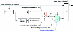
FIGURE 3 — Schematic diagram of macFFD.
Full-color AMOLED with RGBW pixel pattern
A. D. Arnold, P. E. Castro,
T. K. Hatwar, M. V. Hettel,
P. J. Kane, J. E. Ludwicki,
M. E. Miller, M. J. Murdoch,
J. P. Spindler, S. A. Van Slyke,
K. Mameno, R. Nishikawa,
T. Omura, S. Matsumoto
Eastman Kodak Co., U.S.A.
Abstract — A full-color AMOLED display with an RGBW color-filter pattern has been fabricated. Displays with this format require about one-half the power of analogous RGB displays. RGBW and RGB 2.16-in.-diagonal displays with average power consumptions of 180 and 340 mW, respectively, were characterized for a set of standard digital still camera images at a luminance of 100 cd/m2. In both cases, a white-emitting AMOLED was used as the light source, and standard LCD filters were used to provide the R, G, and B emission. The color gamuts of these displays were identical and the higher overall efficiency of the RGBW format results from two factors. First, a large fraction of a typical image is near neutral in color and can be reproduced using the white subpixel. Second, the white subpixel in an RGBW AMOLED display is highly efficient because of the absence of any color filter. The efficiency of these displays can be further enhanced by choosing a white emitter optimized to the target display white point (in this case D65). A two-emission layer configuration based upon separate yellow and blue-emitting regions is shown to be well suited for both the RGBW and RGB formats.
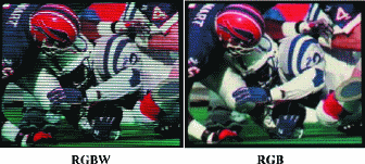
FIGURE 9 — Images from 2.16-in. RGBW and RGB prototype displays.
Surface-discharge electrode design methods for ACPDPs
Shigeki Harada
Akihiko Iwata
Heiju Uchiike
Mitsubishi Electric Corp., Japan
Abstract — In order to lower development costs and to shorten development time, small panels, under 10-in on the diagonal, are used for experiments to improve the luminous efficiency of plasma-display panels. However, it is difficult to show the same results as those of large panels, over 40 in. on the diagonal. In this paper, first, the authors show that the luminous efficiency and the voltage margin of mini-panels are not obtained with large panels by using an actual 46-in. PDP. The reason is that the resistance in the large panels is larger than that in the mini panels and the voltage drop in the large panels are larger than in mini-panels. Therefore, the bus electrode width and the transparent electrode width are important factors in the design of large PDPs. Next, the technique of designing large panels by using a database obtained from mini-panels is described. The estimated cell-design results show good agreement with an actual 46-in. PDP in luminous efficiency and minimum sustain voltage. A large PDP can be obtained by using the cell design proposed in the present paper.
The transmittance though the bus electrode, k, is not simply proportional to the bus-electrode width, because there is a distribution of the luminous intensity in the cell. In order to estimate the luminance without a bus electrode, a panel without bus electrodes has to be obtained. Even in a mini-panel, a discharge, however, does not occur between transparent electrodes without bus electrodes; therefore, we fabricated a special mini-panel shown in Fig. 9(a). The bus electrode and the transparent electrode were formed separately in parallel, and they were connected electrically by electrodes located above the rib. As shown in Fig. 9(b), they are dissociated spatially in the discharge space, but connected electrically. Figure 9(c) shows the intensity distribution of the emission in the cell. The light is not shaded by a bus electrode. Therefore, the luminance without the bus electrode can be measured.
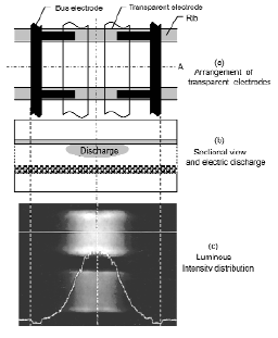
FIGURE 9 — Structure and intensity distribution of the luminance of the experimental panel to the measured luminance without bus electrode L0.