A preview of the papers appearing in the February 2005 issue of theJournal of the SID, available on-line at www.SID.org.
Edited by Aris Silzars
A third-generation timing controller and column-driver architecture using point-to-point differential signaling
Richard I. McCartney
Marshall J. Bell
Abstract — Many assume LCDs will quickly dominate the TV market by simply scaling existing LCD-monitor panels to wider formats (e.g.,16:9 HDTV) and larger sizes. However, a number of TV requirements push beyond the state-of-the-art monitors of today; response time, brightness, contrast, color envelope, color temperature, and progressive scan-and-hold issues require a re-engineering of the monitor solution. Building upon the strengths of LVDS and RSDS technology solutions in digital video-data communications, a completely new architecture that fully addresses the needs of TV while supporting existing LCD-monitor and notebook panels has been created.
Keywords — PPDS, RSDS, Mini-LVDS, cyclic-DAC, R-DAC.
In order to provide a platform from which to significantly advance the performance of the LCD drive-electronics system, we have taken two significant departures from the second-generation architecture. The first is an alternate approach to the standard R-DAC column driver. The second is an alternative to the multi-drop bus architecture, replac-ing it with a direct, point-to-point link between the timing controller and each column driver. One of the keys to cinema-quality images is gray-scale precision and color management. The PPDS™ architecture can support a full 30-bit color precision from input to display surface. Each colored output is capable of more than 12 bits of voltage precision. This precision, coupled with the independent gamma LUT features, allows image processing that greatly enhances the viewer experience.
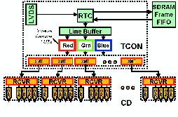
FIGURE 4 — Typical PPDS™ functional diagram.
Scaling-up PECVD systems for large-sized substrate processing
Sheng Sun
Takako Takehara
In Doo Kang
Abstract — Because of the prevailing trend of large-panel TFT monitors and, most recently, LCD TVs, large-sized-substrate processing is becoming the mainstream of TFT-LCD production. To enable this trend of ever-increasing large-area processing, a multiple generations of PECVD systems for volume production has been successfully developed. This paper discusses the scaling-up challenges from the equipment manufacturer's perspective, with the focus on process scalability, system design optimization, productivity enhancement, and cost-of-ownership reduction.
Keywords — PECVD, COO, large-area processing, process scale-up, cost-of-ownership reduction.
Since the turn of the century, the TFT-LCD industry has experienced a major product shift from notebook PCs to desktop monitors. In the coming years, LCD TVs will proliferate and begin to replace CRT TVs with improved quality at a competitive cost. One of the key enablers of large-TFT-panel production with lower cost is the ever-increasing glass substrate size. Already in full production, Gen 5 equipment processes glass substrates measuring ~1100 x 1250 mm2, which can yield 15 up 15-in. or 12 up 17-in. monitors. Aiming for the LCD-TV volume production, Gen 6 and Gen 7 substrate sizes are defined as 1500 x 1800 mm2 and 1870 x 2200 mm2, which can produce 6 up 37-in. and 6 up 46-in. wide TV panels, respectively. Due to the emerging new applications, this substrate-size expansion has exhibited an accelerating trend in the last decade. The mean time to double the substrate size has been reduced to ~1.5 years since 2000, from that of ~4.2 years in the 1990s.
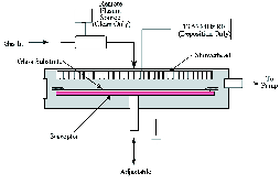
FIGURE 1 — Schematic drawing of AKT PECVD process chamber.
Illumination control system for adaptive dynamic range control
Takashi Toyooka
Shohei Yoshida
Hidehito Iisaka
Abstract — An illumination control system for adaptive dynamic range control has been developed. This system satisfies several performance requirements for image quality and reliability. A projection system using the illumination control system can reproduce images with optimum brightness for each image.
Keywords — Projection, dynamic range, illumination system, psychophysics.
Dynamic range is important for reproducing realistic images. The dynamic range of conventional displays is far inferior to the brightness range existing in the environment. When images are captured by a film camera or video camera, the exposure level is controlled such that the brightness level of the image is adjusted to fit the latitude. Human eyes also control the exposure level and capture the specific brightness range. On the other hand, the dynamic range of a display is determined by the performance of the display device. Dynamic range control (DRC) is a novel display concept for adjusting the overall image brightness and for expanding the image data according to a brightness parameter such as exposure value. Figure 1 shows a conceptual image of DRC. Independently controlling overall light intensity enables an image to be reproduced with brightness faithful to the original.
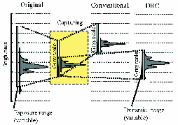
FIGURE 1 — Dynamic-range-control concept.
Super-short-focus front projector with aspheric-mirror projection optical system
Jun Ogawa
Kazuhiro Agata
Mikio Sakamoto
Kunihiko Urano
Takayuki Matsumoto
Abstract — A new front projector with a super-short projection distance of 0.65 m at 100 in. has been developed. A newly developed reflective-type projection optical system in this projector, which was composed of only four aspheric mirrors that were free of color aberrations was installed. Using this new system and a single-chip DMD™, a picture that had excellent sharpness and high contrast from 40 to 100 in. was projected. This paper describes the principles, design, and characteristics of the new WT600™ front projector.
Keywords — Front projector, aspheric mirror, projection distance, projection optical system.
LCD or DMD™ projectors have rapidly been expanding their market share as a presentation tool instead of CRT projectors because of advantages in brightness, resolution, size, and ease of set up. Furthermore, recent improvements in picture quality, particularly contrast, and reduced prices have led to their use in many homes as video projectors. The driving force behind this market expansion is the remarkable technical progress made in improvements in brightness, picture quality, and compactness. There has recently been clamoring demand for a shorter projection distance because set up in confined narrow spaces is increasingly being required in a variety of applications. Moreover, a shorter projection distance also has advantages in enabling decreased depth for rear projectors. To decrease this distance even more and remove color aberrations, a new reflective-projection optical system that is only composed of aspheric mirrors, which has eliminated the need for a refractive lens, has been developed.
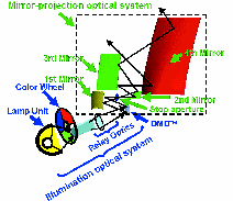
FIGURE 4 — Layout of optical system.
Red-phosphorescent OLEDs employing bis(8-quinolinolato)phenolato-aluminum(III) complexes as emission-layer hosts
Taishi Tsuji
Shin Kawami
Satoshi Miyaguchi
Tsuyoshi Naijo
Toshinao Yuki
Shinji Matsuo
Hiroshi Miyazaki
Abstract — Bis(8-quinolinolato)phenolato-aluminum complexes have been used as emission-layer hosts in red-phosphorescent OLED devices. This enabled high-efficiency long-lived OLED devices with a simple device structure that does not require a hole-blocking layer. Devices with a red-phosphorescent dopant introduced into a noble bis(8-quinolinolato)phenolato-aluminum complex exhibited a high efficiency of 12 cd/A at CIE color coordinates of (0.65, 035) and a long operating lifetime of 30,000 hours or more at an initial luminance of 700 cd/m2. Moreover, triplet–triplet annihilation was reduced in the devices because of the wide emission zone enabled by the complex and the short phosphorescent lifetime of the red-phosphorescent dopant. These red-phosphorescent devices were successfully incorporated into commercial OLED displays.
Keywords — Organic compounds, organometallic complex, phosphorescence, electroluminescent devices, OLED displays, operating lifetime.
The synthesis of 50 types of complexes were considered. Modification of the ligands, i.e., two 8-quinolinolato ligands and a phenolato ligand, changed the ionization potential, carrier mobility, and glass transition temperature of the complexes. One of complexes, which were newly synthesized, exhibited good electroluminescent characteristics and had a glass transition temperature of 110°C or more. This novel bis(8-quinolinolato)phenolato-aluminum complex is referred to as NS11. Triplet-tripletannihilation was reduced in the devices because of the wide emission zone enabled by NS11 and the short phosphorescent lifetime of a UDC red-phosphorescent dopant. These red-phosphorescent devices have been successfully incorporated into commercial OLED displays.
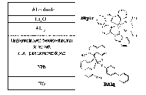
FIGURE 1 — Device structure and typical materials in this study.
Measuring color breakup of stationary images in field-sequential-color displays
Toni Järvenpää
Abstract — Color breakup is an artifact perceivable on field-sequential-color (FSC) displays, both in stationary and in moving images. In this work, a unique device and a method for measuring color breakup on stationary images is proposed. Rotating the field of view of a high-speed measurement camera in milliseconds simulates saccadic behavior. The target can be a virtual display, a direct-view display, or a projector image. Captured images can be used for quantifying the color breakup of a target display. The results along with an exploration of their application to breakup characterization will be presented.
Keywords — Color breakup, field-sequential displays, saccadic eye movement, image quality.
The reason for color breakup on stationary images is not yet clearly understood. Saccadic suppression is believed to inhibit signals from the eye to the brain during saccades, thus maintaining a stable visual world. However, the false colors are observed vividly in the occurrence of a saccade. While the reason for CBU is not clear, the need to eliminate it is. Increasing the frame frequency of a FSC display is the most obvious way of decreasing CBU. Many values have been proposed for the critical frequency after which CBU is no longer perceived. From the author's experiments it seems clear that at least a 3-kHz sub-frame frequency is needed to be sure that the artifact will not be perceived. The typical sub-frame frequency for LCoS panels is currently 360 Hz and it seems unrealistic that panels of over 3-kHz will be needed in the near future.

FIGURE 2 — (a) Image in a FSC display and the path of a saccade. (b) Observed color breakup during or just after the saccade.
Three-dimensional PIC/MC simulations of the sustain discharge pulse in an ACPDP
V. N. Khudik
V. P. Nagorny
A. Shvydky
Abstract — The strong discharge pulse between coplanar electrodes in an ACPDP cell was investigated using fully kinetic 3-D simulations. Key phases in the discharge development were identified and thoroughly illustrated with an extensive set of plots. The main effort is focused on the study of the anode charging wave and striations formed above the dielectric surface in the anode area. To elucidate these physical phenomena, a number of specially designed numerical experiments were performed.
Keywords — ACPDP, PIC/MC simulation, PDP discharge, striations, cathode fall.
In a strong discharge in an ACPDP cell with a small distance between sustain electrodes, the physical phenomena in the cathode and anode areas weakly influence each other and are connected largely by the current through the plasma channel. As the discharge develops between coplanar electrodes, it deposits the positive charge on the dielectric surface above the cathode and the negative charge on the surface above the anode. Both processes progress in a wave-like manner with quite pronounced wavefronts.

FIGURE 3 — Distribution of the ion density (top view) when ion velocity is artificially set to zero in the left-hand part of the PDP cell (on the left from the dashed gray line).
Étendue-density homogenization lamps with light concentration function
A. Sekiguchi
Y. Goto
Abstract — In order to increase the screen brightness of Digital Micromirror Device™ projectors (DMD™ projectors), a new compact lamp was designed. In previous work, a lamp that has an aspherical lamp reflector and an aspherical front glass, which are called EHLa, was discussed. Although they improve the light convergence at the entrance of rod integrators, they require external lenses for light condensation. A new EHLa that can converge light without the need for external lenses will be discussed. The new lamp corresponds to conventional elliptic reflector-type lamps, which are widely used for mobile-type DMD™ projectors. Simulations demonstrated that the ratio of increased brightness is 17.1% for the new lamp design versus conventional lamps in a 0.7-in.-diagonal DDR DMD™ panel.
Keywords — DLP, DMD, multi-lens, aspherical, integrator, high-pressure, mercury lamps, projectors, etendue matching.
Coupled with high-pressure mercury lamps, rod integrators are widely used in DMD™ projector optics. It is well known, however, that the light loss at the rod integrator entrance sometimes becomes very significant. The loss is caused mainly by the mismatches in size between the lamp's arc and the cross section of the rod integrator. The rod's cross-section size is directly proportional to the image area size of the DMD. With the recent trend toward using smaller DMD™ panels, it is easy to understand that the mismatches mentioned above will become even larger, resulting in even greater light loss. In previous work, the same problem was discussed and two solutions, EHLe and EHLa, were given.
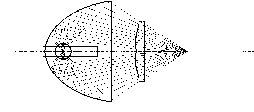
FIGURE 5 — Compact-type EHLa.
Driving large-sized OLED TVs with an amorphous-silicon backplane
Takatoshi Tsujimura
Frank Libsch
Paul Andry
Abstract — A 20-in. OLED display driven by an amorphous-silicon backplane has been demonstrated. It has been widely believed that the characteristics of amorphous-silicon TFTs are not sufficient to drive OLED displays. This paper challenges this hypothesis and proves that amorphous silicon can be applied to large active-matrix-driven displays and discusses many possible approaches that lead to good front-of-screen quality. Superior-video-image-quality amorphous-silicon-driven OLEDs open a bright future for a new generation of wall-hanging televisions.
Keywords — Amorphous silicon, TFT, OLED, thresold-voltage shift, television.
OLED technology is equipped with outstanding features for television application, such as a superior video image, a wide color gamut, punching capability, wide viewing angle, and low cost. Because polysilicon backplanes have size limitations, a new backplane technology that can eliminate the size limitation is desired. Although a-Si TFT backplanes have almost no size limitation up to 2 m, there are two issues, conductivity and instability, that need to be solved in order for a-Si TFTs to be capable of driving large-area OLED displays. By combining various new methods and the thorough investigation of a-Si degradation, the world's largest 20-in. OLED was fabricated with a-Si TFTs, which was previously believed not to be possible.

FIGURE 15 — A 20.0-in. a-Si driven OLED display.
PC display resolution matched to the limits of visual acuity
Brent Baxter
Philip Corriveau
Abstract — This experiment determined the maximum useful resolution for a desktop PC display. In the absence of limitations attributable to the display, it was assumed that the eye's spatial resolution determined the minimum-size that letters could be recognized. A spatial-resolution limit representing the display was introduced and the size applied to 16 upper-case letters was increased until observers again had difficulty recognizing the letters. The eye and display affected text recognition equally when the size of the just-recognizable letters had to be 1.5x larger than when the display's effect was absent. An analysis of the results indicated that the eye's visual acuity and display resolution are of approximate equivalence when a 186-dpi display is viewed at a distance of 46 cm (18 in). Comparable results were observed for three additional stimulus types: text-like nonsense symbols, gray-scale PC computer icons, and the same computer icons with colored features.
Keywords — PC display, visual acuity, spatial resolution, text recognition.
It is common in the PC industry to hear assertions that displays having pixel densities of 200–250 dpi represent a practical upper limit beyond which further increases do not give much additional benefit. Data show that 186 dpi is the point of equivalence between visual acuity and display resolution. This is consistent with the view that only diminishing benefit may be expected at higher dip values.
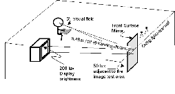
FIGURE 2 — A 5.45-m (18 ft.) viewing distance minimized artifacts due to the laboratory display.
Contrast of displays on the retina
G. C. de Wit
Abstract — When the eye projects an image on the retina, contrast degradation takes place because of stray light in the eye. This letter shows that for a 24 x 18° display, the maximum achievable retinal contrast for a 4 x 4 checkerboard image is approximately 80:1 for young persons, going down to approximately 37:1 for a 70-year-old person. This information is important for both display consumers and manufacturers because it puts the display contrast specification into perspective and may affect the contrast design target of a display system.
Keywords — Displays, contrast ratio, dynamic range, ocular stray light.
Manufacturers of (near-to-eye) displays often specify the inherent contrast ratio (or contrast in short) of their displays. However, the contrast perceived with the eyes is different from that of the display because of ocular light scattering. In this letter, the contrast-degradation contribution of the eye is determined so that the inherent display contrast values can be put into perspective.
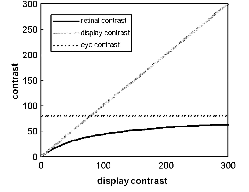
FIGURE 2 — Retinal contrast as a function of display contrast with a characteristic young-eye contrast value of 80:1.