A preview of the papers appearing in the August 2005 issue of the Journal of the SID, available on-line atwww.SID.org.
Edited by Aris Silzars
Magnetic ring for convergence improvement in CRTs with rectangular DY aperture
René Fierkens
LG.Philips Displays Netherlands
Abstract — In order to meet customer specifications in CRT production, it is common use to apply methods to improve the dynamic-convergence performance. The dynamic-convergence performance of CRTs can be improved by employing Magnetically Improved Color Alignment (MICA) technology. This involves the writing of the appropriate magnetic correction profile into a ring. The ring consists of hard-magnetic ferrite particles embedded in polypropylene material and is inserted into the deflection yoke (DY) after the writing process is completed. MICA technology has been proven for a CRT with a rectangular DY aperture, 32-in. WSRF (wide screen real flat) slim CRTs. MICA offers a good alternative to conventional dynamic-convergence improvement methods such as spoilering and coil exchange.
A technology has been developed to improve the dynamic-convergence performance: MICA (Magnetically Improved Color Alignment). Basically this is carried out as follows: (a) The actual convergence performance of a rejected tube coil assembly (TCA) is measured. (b) The deflection yoke (DY) is removed from the tube. (c) The appropriate magnetic correction profile is written into a hard-magnetic permanently magnetizable ring. (d) The recorded ring is clicked into the DY. (e) Tube and DY, including the MICA ring, are re-matched, resulting in a TCA that meets customer specifications. The ring consists of ferrite particles embedded in polypropylene material.

FIGURE 8 — Example of a magnetic correction profile recorded into the MICA ring [X-axis: increments on ring circumference, starting from the North position on the ring; Y-axis: magnetic field strength (kA/m)].
A deflection yoke for projection TV with reduced geometrical distortion
T. Yoshinaga
K. Iwasaki
Matsushita Toshiba PictureDisplay Co., Ltd.
Abstract — The raster-distortion and deflection-defocusing problems in CRT projection TV have been minimized by utilizing a longer horizontal coil and uniquely shaped windings. The field distribution along the tube axis was also modified and optimized to achieve minimum raster distortion and deflection defocusing simultaneously. The position of the centering magnet was shifted towards the screen side to minimize the defocusing of the spot.
A longer and uniquely shaped horizontal coil has been developed as follows: (1) The length of the horizontal coil in the screen section was extended. (2) The bent-up area of the horizontal coil at the screen section is concaved to keep the optimum distance between the horizontal coil and high-voltage button (see Fig. 12). In order to design the horizontal coil length, a simulated method that introduced the idea of a geodesic line was applied. The horizontal deflection power becomes larger by using a longer horizontal coil. The horizontal deflection power was maintained by making the coil longer at the gun portion.
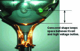
FIGURE 12 — Structure of the new horizontal coil (installed H-coil on a CRT).
Technologies towards patterned optical foils applied to transflective LCDs
B. M. I. van der Zande,
C. Doornkamp, S. J. Roosendaal,
J. Steenbakkers, A. Op't Hoog,
J. T. M. Osenga, J. J. Van Glabbeek,
L. Stofmeel, J. Lub,
M. Shibazaki, K. Asahara,
M. Shibazaki, T. Inada,
M. Yoshiga, S. Kawata
Philips Research Laboratories
Abstract — For better front-of-screen performance for transflective LCDs, a technology with extra free optimization parameters for the optical stack is needed. Thin wet coatable retarders that enable adjustment of the optical activity on the (sub)pixel level have been developed. Isotropic domains have been created in nematic retardation films by thermal patterning or photopatterning. Employing such a patterned retarder in a transflective LCD leads to an LCD that is lighter and thinner with good reflectivity, high transmission, and low chromaticity at all gray levels and wide viewing angles. The patterned thin-film technology has been proven to be versatile and applicable in various LCD designs.
The use of an optical film with different effective birefringence values in the reflective and transmissive part of the pixel creates the required free parameters to optimize both the transmissive and reflective modes simultaneously. The technologies needed to manufacture patterned retarders are versatile: Photoalignment, thermal processing, or pure photolithographic processes can optionally be used, creating minimum impact on mass-production lines. Thermally stable films with alternating birefringent and isotropic domains can be prepared by thermal patterning technology, i.e., photopolymerizing through a mask in the birefringent state, followed by complete exposure of the film after heating above the clearing point, or by the photopatterning technology, i.e.,photoisomerizing through a mask to isotropize the birefringent state, followed by complete exposure of the film at room temperature to photopolymerize both isotropic and birefringent domains.
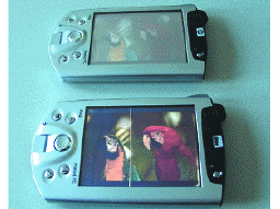
FIGURE 9 — The bottom PDA contains a transflective display equipped with a thermally patterned retarder, whereas the upper PDA makes use of a conventional retarder.
Double-faced TFT-LCD having one LC panel and one lighting system
Tokio Taguchi, Kazuhiko Tsuda,
Yasuhisa Itoh, Naofumi Kimura
Sharp Corp.
Abstract — A novel liquid-crystal-display (LCD) system referred to as a "Double-Faced LCD" has been developed. It has only one LC panel and one lighting system, but it works not only as a transmissive-type LCD from one side but also as a reflective-type LCD from the other side. Therefore, the thickness and the weight of the Double-Faced LCD can be reduced compared to those of conventional LC modules that have two LC panels and two lighting systems.
A Double-Faced LCD works not only as a transmissive-type LCD fromone side but also as a reflective-type LCD from the other side. Figure 1 shows the schematic and operation principle of this device. It has a front lighting system, an LC layer, two polarizers, and a reflective polarizer. In this figure, transmission axes of polarizer-1 and polarizer-2 are orthogonal. The reflective polarizer is placed between the LC layer and polarizer-2, and the transmission axes of the reflective polarizer and polarizer-2 are placed parallel to each other. The reflective polarizer transmits linearly polarized light parallel to the cross section and reflects that light perpendicular to the cross section. This device works just like a conventional transmissive-type LCD when viewed from the polarizer-2 direction and works as a reflective-type LCD from the polarizer-1 direction.
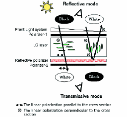
FIGURE 1 — Schematic representation and operation principle of the Double-Faced LCD.
Laser Thomson scattering and optical emission studies of striated PDP micro-discharge plasmas
Safwat Hassaballa, Yasushi Sonoda,
Kentaro Tomita, Young Kee Kim,
Kiichiro Uchino
Interdisciplinary Graduate School of Engineering Sciences
Abstract — Properties of a plasma-display-panel (PDP) like discharge were examined by emission and laser Thomson scattering (LTS) measurements. Emission measurements were performed using an intensified CCD camera. By varying several external parameters such as the amplitude of the input voltage, gas composition, and pressure, the influence of these parameters on the discharge behavior was studied. Results of emission measurements showed that they were in good agreement with similar emission measurements on real PDP cells. LTS measurements were performed for the striated PDP-like discharge at a pressure of 100 Torr and the results showed clear modulations in both profiles of electron density and electron temperature.
Some of the basic discharge features occurring in an ACPDP-like discharge as deduced from LTS measurements and the optical emission (OE) measurements using an intensified charged-coupled device (ICCD) will be discussed. This detailed emission study has two main objectives. First, to investigate whether the PDP-like discharge system used for LTS measurements is reproducing the main features of the real PDP cell discharge or not. Second, choosing the suitable conditions for performing LTS measurements at different experimental conditions. Compared to LTS measurements, the OE measurements are less time consuming and require a simpler experimental setup.
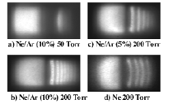
FIGURE 3 — Emission images taken by the ICCD camera for different pressures and different Ar percentages.
A light and flexible plasma tube array with a film substrate
H. Hirakawa, K. Awamoto,
M. Ishimoto, K. Shinohe,
A. Tokai, H. Yamada,
Y. Yamazaki, T. Shinoda
Fujitsu Laboratories
Abstract — The plasma tube array is expected to lead to the realization of wall-sized displays. This method will realize an emissive-type display with a flexible screen and an expandable screen size. A plastic film substrate with display electrodes for use as a flexible screen was investigated and the world's largest bendable emissive display (1000 x 128 mm) was successfully developed. The operating voltage distribution was improved compared to that with a plate substrate, and a sufficient voltage margin was maintained.
By optimizing the discharge gap, a luminous efficacy of 2.7 lm/W was achieved. And the highest luminous efficacy of 3.7 lm/W was achieved by using a rectangularly shaped plasma tube. However, the flexural strength of the rectangularly shaped plasma tube was not high enough, so we finally adopted a cylindrically shaped plasma tube. A 1 x 128 mm test PTA composed of 128 plasma tubes 1 m long was successfully manufactured. A luminous efficacy of 3.1 lm/W was achieved, and it is much higher than that of commercial PDPs.
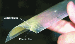
FIGURE 7 — Flexible plastic film and PTA.
Estimating text legibility of a mobile display on the basis of translational vibration caused by walking
Maria Olkkonen
Terhi Mustonen
Nokia Research Center
Abstract — In this study, the effect of vibration on mobile-phone text legibility caused by walking was examined. Legibility was measured as reading performance and subjective task load when reading from a mobile-phone display while walking on a treadmill at 1.5 km/hour, 3 km/hour, and an individually defined speed (3.9 km/hour on average). Vibration was measured on the vertical, lateral, and fore-and-aft axes during walking. Vibration amplitude was calculated in five different frequency bands (1, 2, 4, 8, and 16 Hz) and correlated with the legibility measures. The amplitude increased most on the vertical and fore-and-aft axes as a function of walking speed, and the increase was largest in the 2-Hz frequency band. Legibility decreased concurrently with increasing vibration. The strong correlation between vibration characteristics and legibility measures suggests that vibration characteristics could, to some degree, be used in estimating small-display legibility while walking.
Reading performance was deteriorated even at a slow walking speed and the effect grew stronger as the speed increased. Also, self-reported task load, especially physical demand, increased with the amount of vibration. Together with the degradation of performance, this suggests that the subjects were trying to compensate for the adverse effects of the vibration. The negative influence of vibration might be explained by the system of coordinated eye movements that is typically used to compensate for self-induced motion. It can be hypothesised that this controlling system was not fully able to compensate for the effect of the frequencies present during the reading task.
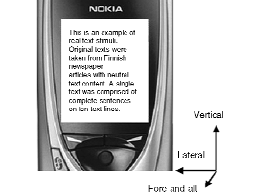
FIGURE 1 — An example of the reading stimuli. Vibration axes: vertical, lateral, and fore-and-aft are shown next to the stimulus.
Stereoscopic 3-D display with optical correction for the reduction of the discrepancy between accommodation and convergence
Takashi Shibata
Takashi Kawai
Keiji Ohta
Masaki Otsuki
Nobuyuki Miyake
Yoshihiro Yoshihara
Tsuneto Iwasaki
Waseda University
Abstract — A method for reducing the discrepancy between accommodation and convergence when viewing stereoscopic 3-D images is described. The method uses a newly developed stereoscopic 3-D display system with a telecentric optical system and a mobile LCD. The examination of a mono-focal lens showed that a correction lens having the appropriate refractive power and conditions for presenting stereoscopic 3-D images clearly reduces the discrepancy between accommodation and convergence. The authors also developed a stereoscopic 3-D display that uses dynamic optical correction to reduce the discrepancy between accommodation and convergence. The display equalizes the theoretical points of accommodation and convergence. The purpose of the development was to expand the regeneration range of a stereoscopic 3-D image having the appropriate accommodation. An evaluation of the developed display showed that it resolves the discrepancy between convergence and accommodation.
The discrepancy in visual representation is the result of the ambiguous depth information produced by accommodation and convergence. The discrepancy arises because accommodation is fixed for a particular display, while convergence determines the position of the represented 3-D image. In natural vision, accommodation and convergence produce identical depth information. This discrepancy is a major problem for stereoscopic 3-D displays since it causes visual fatigue in the observer.
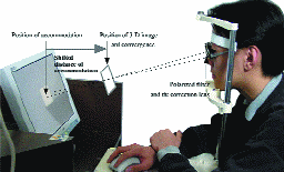
FIGURE 2 — Scene of the image presentation without the discrepancy in visual representation.
Influence of x-ray irradiation on doped europium in BaMgAl10O17 studied by x-ray absorption fine structure and x-ray diffraction
Ichiro Hirosawa, Tetsuo Honma,
Kazuo Kato, Naoto Kijima,
Yasuo Shimomura
Japan Synchrotron Radiation Research Institute
Abstract — The influence of x-ray irradiation on the doped europium ion in BaMgAl10O17 (BAM) by x-ray absorption fine structure measurement and x-ray diffraction was studied. It was found that x-ray irradiation promoted oxidation of doped europium and fading emissions. However, no difference was found in x-ray diffraction patterns before and after x-ray irradiation. It was concluded that the fading of BAM after x-ray irradiation was mainly caused by oxidation of the doped europium in the BAM.
PDP images are generated by controlling the luminance of three colors emitted from metal-oxide phosphors, such as Y2O3:Eu, (Y,Gd)BO3:Eu, Zn2SiO4:Mn, and BaMgAl10O17:Eu. These phosphors emit visible light by irradiation of the characteristic vacuum ultraviolet (VUV) light emissions of the Xe plasma in the PDP. Europium-doped BaMgAl10O17 (BAM) is widely used as blue phosphor in the PDP. However, degradation resulting after annealing and irradiation by ultraviolet light are serious problems in using BAM in PDPs. Up to now, much work on the problems with BAM has been reported; however, the details of the operating and annealing degradations remain unclear.
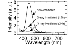
FIGURE 1 — Photoluminescence spectra from the pellets of BAM before and after x-ray irradiation excited by 146-nm UV light.
Effect on deoxidation of doped europium in oxidized BaMgAl10O17
Tetsuo Honma
Ichiro Hirosawa
Naoto Kijima
Yasuo Shimomura
Hajime Yamamoto
Japan Synchotron Radiation Research Institute
Abstract — The effect of the deoxidation of oxidized blue-light-emitting europium-doped BaMgAl10O17 (BAM) phosphor in a plasma-display panel was studied by making photoluminescence and powder X-ray diffraction measurements and by X-ray absorption fine structure analysis. Photoluminescence spectra, powder X-ray diffraction and X-ray absorption near-edge structure, and extended X-ray absorption fine structure spectra of BAM at the europium L3-edge suggest that the oxidized BAM annealed in air is revived by heating in a H2/N2 (5% H2) reducing atmosphere above 500°C.
Blue light emission from BAM decreases because of annealing in the PDP fabrication process. The development of PDP fabrication process that does not degrade blue light emission from BAM is a major objective. An investigation into suppressing the fading of blue light emission from BAM was carried out. The fading of blue light emission from BAM occurs because annealing in air causes oxidation by diffused oxygen atoms that diffuse into an ionic conduction layer, according to our XAFS investigation. We found that europium is oxidized without modification of the crystal structure by annealing in air and that degradation of BAM was caused by oxidation of europium in an ionic conducting layer. Thus, annealing oxidized BAM in a reducing atmosphere may revive the photoluminescence characteristic through deoxidation of doped europium.
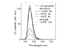
FIGURE 1 — Photoluminescence spectra of non-annealed BAM, annealed BAM at 600°C in air for 16 hours and deoxidized BAM in a H2/N2 (5% H2) reducing atmosphere excited by 146-nm UV light.
Color-conversion method for a multi-primary display to reduce power consumption and conversion time
Masanori Takaya
Ken Ito
Gosuke Ohashi
Yoshifumi Shimodaira
Shizuoka University
Abstract — A color-conversion method for a light-emitting multi-primary-color display is proposed. While a multi-primary-color display uses four or more primary colors to reproduce a wide color gamut, multiple sets of primary-color signals are needed to reproduce one color. Therefore, linear programming, which results in low power consumption, was adopted to uniquely determine the set of primary-color signals. Although a highly accurate color conversion was achieved by using linear programming with low power consumption, it requires a very long time to convert colors of high-resolution images. Therefore, by categorizing the color conversion of linear programming as a classification problem, colors are converted by using the decision-tree method, which is a classification method. As a result, color conversion with high accuracy, low power consumption, and short conversion time was achieved.
The decision tree is one of the discrete classification methods based on the machine learning technique. We adopted the decision tree to detect the optimal set of non-basic solutions of linear programming to convert color with low power consumption because it is suitable for problems dealing with linear space. The decision tree classifies input data into an optimal class by using constructed trees or rules. Figure 6 shows the missing data caused by the decision tree and LUTs on the SHIPPXYZ color chart. In Fig. 6, data colored black indicate the missing data. The missing data of decision tree are very small in comparison with those of LUTs. Therefore, the conversion of decision tree with complementation is 40 times faster than that of linear programming, and the time of decision tree is shorter than that of LUTs.
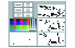
FIGURE 6 — Missing colors of the LUT and decision tree on a SHIPP color chart.
Optimization of liquid crystals for television
Detlef Pauluth
Kazuaki Tarumi
Merck KGaA
Abstract — LCD TVs have dramatically improved in performance during the last 2 years. At the same time, the sale prices decreased by more than 50%. Together with the introduction of digital terrestrial broadcasting, this resulted in increasing sales of LCD TVs. This paper gives an overview of the main liquid-crystal display (LCD) technologies used for TVs. Key materials, synthesis, structural property relationships, and the optimization of LC mixture properties will be discussed. For all technologies, fast-switching LC mixtures (16 msec) have been achieved. Novel materials for LC mixtures for the next generation of superior performance LCD TVs with 8-msec switching times are shown.
The main material research target is synthesis and identification of compounds with lower viscosity while maintaining or even improving the other properties. Computer simulations for the calculation of Δε and Δn based on molecular properties, such as dipole moments and polarization are often in good agreement with measured values of LCs. Calculated electrostatic potentials give useful hints for the so-called reliability parameters. Computer simulation of bulk properties such as elastic constants, viscosities, and melting points, on the other hand, are still in an early stage. The most promising LCD technologies at the moment are VA and IPS due to their unique combination of very good contrast, wide viewing angle, and fast switching times. These technologies will dominate larger TV screens over 30 in. on the diagonal. A significant growth for LCD TVs is forecasted, resulting in a share of about 20% of the total TV market in 2007.
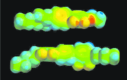
FIGURE 2 — Space-filling models of compounds 5 and 10. The color is visualizing electrostatic potentials. Blue represents a positive electrostatic potential (ESP) and red represents a negative electrostatic potential. In the oxygen-containing compound 5, the ESP is more concentrated compared to tetrafluoroterphenyl 10.