ITO Coating of Glass for LCDs
Sputtering ITO from planar targets has been a very successful process in LCD manufacturing, but the move to rotating cylindrical targets can substantially lower the cost of coating a substrate.
by Wilmert De Bosscher, Krist Dellaert, Steven Luys, and Ann Lacres
AS manufacturers strive to meet the growing demand for flat-panel displays (FPDs), street prices continue to drive their adoption, but in many cases inhibit their use. The cost of panels account for a significant percentage of the total cost of liquid-crystal displays (LCDs). Therefore, reducing the production costs of the panels is of critical importance to market growth. Indium tin oxide (ITO) layer coaters – a critical link in today's FPD supply chain – can look forward to new technologies that will help reduce production costs.
Cylindrical Targets
In industries such as the architectural glass-coating industry, rotating cylindrical magnetrons have been successfully used since the 1990s. Cylindrical-target materials were developed in parallel, primarily to allow for the fabrication of low-emissivity and solar-control coating stacks. But early rotatable sputter technology was not robust enough to meet the stringent requirements of flat-panel technology, so the development of cylindrical ITO targets was put on hold.
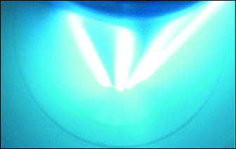
DC magnetron sputter deposition from a ceramic planar ITO target is still the most common method used in the application of ITO coating on glass or plastic substrates. But planar magnetrons have several limitations, and advances in both hardware and consumables for rotating cylindrical magnetron technology are now producing excellent results in field tests on display applications. Specifically, performance and cost advantages are being realized by using rotating cylindrical magnetrons and rotating cylindrical ceramic ITO sputtering targets in display coating (Fig. 1).
Rotating Cylindrical Magnetrons
ITO is one of the top-performing transparent conductive oxides (TCOs) available to the display industry. Applications include transparent electrodes for FPDs, such as LCDs, plasma-display panels (PDPs), and organic light-emitting diodes (OLEDs). TCO thin films are preferred for such applications because they combine high optical transmittance and high electrical conductivity – and ITO is the TCO of choice for a wide variety of applications. In addition to its desirable electrical and optical properties, ITO is hard and has good chemical and thermal stability.
 Bekaert Advanced Coatings N.V.
Fig. 1: Shown is a plasma discharge in a rotating cylindrical magnetron used for ITO deposition.
Reactive DC magnetron sputter deposition from a planar ceramic target is currently the most extensively used technique for the reliable and cost-effective deposition of ITO coatings on glass and plastic substrates. But planar targets typically consist of one or more tiles bonded to a metallic backing plate, and they have several significant limitations, including limited target lifetime and the resulting downtime.
Rotating cylindrical magnetrons and advanced rotating cylindrical ITO targets promise to overcome the limitations of planar targets. They permit manufacturers to increase coating throughput while maintaining, and even improving, layer quality and layer-thickness uniformity.
Advantages of Rotating Cylindrical Magnetrons
Lower Cost. A cylindrical target can contain three times the amount of material as a planar target of similar thickness. Cylindrical targets also have a superior degree of utilization – the percentage of target material that can actually be used. Typically, utilization is more than 80%, or 2–3 times that of planar targets.
For planar magnetrons, the presence of a "racetrack-shaped" zone – the localized plasma zone where erosion from sputtering occurs – limits the target lifetime, thus increasing the cost of ownership.
In a planar magnetron, a magnetic system located below the planar target material generates a magnetic field above the target surface. The magnetic-field distribution forces the electrons that leave the target surface to drift within the closed-loop magnetic bottle. In this racetrack-shaped zone, interactions between the magnetically trapped electrons and gas atoms create ionization in a local plasma region and causes local sputter erosion of the target material due to the impact of positive ions on the target cathode.
The closed-loop plasma zone is stationary, defined by the position of the magnets, and contains the majority of energetic free electrons above the surface of the target. The direction of deposition is primarily perpen-dicular to the target surface where the plasma is present. Target material is consumed where the plasma is most intense, leaving the majority of the material untouched, which produces poor material utilization rates.
In a rotating cylindrical magnetron, a stationary magnetic system located inside a rotating cylindrical target tube generates a stationary racetrack-shaped zone, which defines a specific direction of sputtering and deposition inside the coating chamber. Because the tube rotates below the local plasma, the time-dependent local erosion zone spreads over the complete circumference of the target tube, resulting in an equal amount of erosion over the entire tube. This produces very high material utilization rates, much longer production runs, and reduced downtime of the machinery, which translates into increased throughput of the coating equipment. Because of the rising cost of targets, better utilization of materials is key to reducing production costs.
Increased Deposition Rate. The power density of planar targets is limited because the target material may melt or crack under the local thermal load. Rotating cylindrical targets sustain higher power densities because the thermal load is uniformly distributed over the entire circumference of the target. This results in less local heating of the water-cooled target tube.
Reduced Arc Sensitivity. Rotating cylindrical magnetrons have much less arc sensitivity in reactive processes than planar magnetrons because rotating cylindrical targets restrict the arcing zone to two ring-shaped areas at the cathode-tube ends. Very little arcing occurs in the racetrack-shaped zone of a rotating cylindrical target because it is continuously cleaned by the plasma, and only a thin zone at the extreme ends of the target tubes becomes contaminated. This superior process stability benefits both the layer quality and deposition speed in reactive processes.
Table 1: Configurations for Rotating Cylindrical Magnetrons in Display Coaters
| • Substrate close to the opening; magnetron completely within the door |
• Cantilevered magnetron |
| |
• Double-sided end-block concept |
| • Substrate further away from the opening; magnetron completely within chamber |
• Double-sided end-block concept |

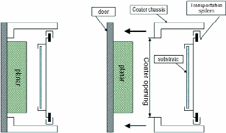
Fig. 2: This cross section of a typical display coater, viewed perpendicular to the direction of glass movement, indicates that the position of the coater opening relative to the position of the substrate makes it difficult to introduce a rotating cylindrical magnetron.
Reduced Debris Generation. The plasma zone on a rotating cylindrical magnetron is very much narrower than that on a planar magnetron, so the ejected target particles are more effectively focused towards the substrate in between the trimming shields. This may result in less shield contamination, a reduced chance of flaking, a reduced need for shield exchange or cleaning, and an increased sputter yield on the substrate because less material accumulates on the shields.
Implementation in the Display Industry
There are several historical reasons why the rotating cylindrical magnetron is the standard in many applications, though remains limited in the display industry. A decade ago, the display industry was focused on smaller glass substrates, and coaters were typically Gen 2 and Gen 3 coaters. Sputter coating was often performed in cluster tools with stationary substrates and large rectangular targets, or in smaller in-line coaters with moving substrates and long rectangular targets. For those configurations, planar magnetrons were an easy solution, and ITO targets were only available in planar tiles.
Since then, the size of FPD substrates has increased tremendously, with typical glass substrates currently 10–20 times larger than it was 10 years ago. In this new environment, the use of rotating cylindrical magnetron technology makes perfect sense.
Because the cost of rotating cylindrical magnetrons does not scale with substrate or target sizes, they are a cost-effective alternative for large architectural-glass coaters (which can handle substrates up to 3.2 x 6 m). Currently, the cost of a complete rotating cylindrical magnetron is on the same order of magnitude as the cost of a single ITO target. As a result, nearly all the benefits of using rotatable technology are bottom-line profit, almost independent of the retrofitting cost.
But adopting a new and promising technology to replace a proven technology is not an easy task, as we at Bekaert learned from our experience bringing cylindrical targets and sputter hardware to the large-area glass-coating market in the early 1990s. But now, cylindrical targets are used successfully in large-area glass-coating lines all over the world. Understandably, we would like to leverage this experience and implement a similar technology switch in the display industry.
In the past, the design of specific vertical coaters complicated retrofitting. This problem is currently addressed by the creation of a compact end block that takes up only a fraction of the space used by standard end blocks and can be easily retrofitted into the planar cathode space. The use of cantilevered magnetrons can also be used in certain configurations. The end result is that the replacement of planar cathodes with rotating cylindrical magnetrons will no longer result in shorter target lengths or a reduction in uniform coating width.
There are two possible configurations and associated concepts and approaches for using rotating cylindrical magnetrons in display coaters (Table 1).
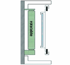
In today's typical planar display coaters, the coater opening relative to the position of the substrate restricts the possibilities for introducing a rotating cylindrical magnetron (Fig. 2). If the substrate is located farther away from the coater opening, a vertically mounted end-block system will help attain the correct target–substrate distance (Fig. 3).

Fig. 3: If the substrate is located farther away from the coater opening, a vertically mounted compact-end-block system will allow for the installation of a rotating cylindrical magnetron and still maintain the correct target–substrate distance.
Fig. 4: If the substrate is located closer to the coater opening, it is possible to mount a cantilevered magnetron, which can be integrated quite easily in new-generation display coaters.
A cantilevered magnetron, which is mounted on a horizontal plane, is difficult to integrate in this case because of interference with the sealing surface of the door. If the substrate is located closer to the coater opening, top or bottom mounting of a cantilevered magnetron becomes possible and can be integrated quite easily in new-generation display coaters (Fig. 4).
Conclusion
As the manufacture of FPDs becomes a more mature process, it becomes even more important for the display industry to find ways of reducing the cost of ownership of process equipment and the bottom-line cost of coated substrates per unit area. This is not only achieved with a markedly increased machine throughput and coating capacity – thanks to an increased target-material inventory and power density – but also by an enhanced utilization of targets consisting of very expensive materials.
Because of the advances made in its technology, process, and engineering, rotating cylindrical magnetron sputtering has become one of the most economical technologies. The new hardware for this procedure can be installed with minimum downtime. Preliminary field tests shows that costs can be reduced by as much as 40% per square meter while target utilization doubles. •
Wilmert De Bosscher is Technology and Key Learning Manager at Bekaert Advanced Coatings N.V., Karreweg 20, B-9870 Zulte, Belgium; telephone +32-9-240-95-63, e-mail: Wilmert.debosscher@bekaert.com. Krist Dellaert is Technology Manager, Sputter Mechanics; Steven Luys is Product Market Manager, Sputter Products; and Ann Lacres is Marketing Manager at Bekaert Advanced Coatings.